How to extrude blender
How to extrude blender
Extrude – экструдирование
В Blender трансформация Extrude позволяет создавать новые грани, вершины и ребра мешей путем своего рода выдавливания, чаще всего граней. Грань, к которой применяется данная трансформация, при этом не дублируется, а переносится. Extrude переводится как «выдавливать».
На рисунке ниже левая фигура была получена из куба простым перемещением верхней грани с последующим ее уменьшением. Для верхней грани правого куба было применено экструдинование, после этого грань уменьшили. Видно, что во втором случае были созданы дополнительные вершины, ребра и грани. Сама верхняя грань была перемещена, а не дублирована, то есть внутри куба нет «перегородки».
Хотя выдавливалась только верхняя грань, при этом были автоматически созданы связующие боковые грани.
Инструменты экструдирования становятся доступными в Edit Mode, находятся в регионе инструментов.
Однако в случае регионального выдавливания удобнее использовать горячую клавишу E. Если вы пользуетесь не горячей клавишей, а включаете инструмент, появляется специальный маркер, помогающий выполнять экструдирование.
Зажатие левой кнопкой мыши желтого значка с плюсом приводит к выдавливанию по нормали – оси, перпендикулярной в данном случае плоскости. Если кнопка мыши зажимается внутри белой окружности, выдавливание будет произвольным.
При экструдировании надо понимать, что такое глобальная и локальная система координат, а также нормали. Это важно, когда выдавливается стразу несколько элементов. Можно сделать так, что все будут выдавливаться в одну сторону или же каждая в свою.
Когда куб стоит в исходной позиции, его локальная система координат совпадает с глобальной. Однако, если мы его повернем, и переключимся на локальную систему координат, то увидим разницу.
Если взять за начало системы отсчета опорную точку куба, то поворот или перемещение самого куба перевернет или переместит его систему координат. Куб на рисунке был повернут по оси X на 45 градусов. В результате его локальная система координат перестала совпадать с глобальной, которая остается единой для всех объектов на сцене. Локальная же у каждого объекта своя.
Поскольку мы выдавливаем отдельные элементы объекта, то локальная система координат всего объекта не имеет большого значения. Куда важнее понятие нормали. В случае грани, нормаль – это воображаемая прямая, перпендикулярная грани.
На рисунке выше, если мы будем выдавливать верхне-левую грань вдоль оси Z, в случае выбора глобальной оси грань уйдет вверх. В случае нормали грань будет выдавливаться на северо-запад.
При нажатии E сразу предлагается выдавливать по нормали (появляется цветная линия-подсказка, обозначающая нормаль), потому что так делают чаще. Однако, нажимая Z, вы можете изменить поведение вплоть до произвольного экструдирования. В каком режиме вы находитесь, пишется в верхнем левом углу редактора.
Можно выбрать другую ось, нажимая X или Y. Повторное нажатие этих клавиш также будет чередовать от нормали до произвольного выдавливания.
Обратите внимание, чтобы иметь возможность выдавливать вдоль глобальных осей, заранее должна быть установлена глобальная система координат.
Региональное и индивидуальное выдавливание
Разница между региональным (E) и индивидуальным (Alt + E → Extrude Individual Faces) выдавливанием есть, когда операция выполняется сразу над несколькими гранями, расположенными под разными углами.
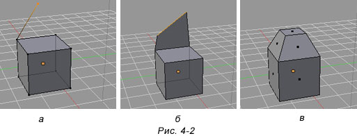
Когда выдавливается несколько граней и используется Extrude Region вычисляется некая средняя нормаль и вдоль нее двигаются все новые грани. Если же используется Extrude Individual, каждая грань будет выдавливаться вдоль своей личной нормали (Z в этом случае не работает). На изображении ниже для верхней и боковой граней левой фигуры было использовано Extrude Region (средняя нормаль обозначена фиолетовой линией), для правой фигуры – Extrude Individual.
Выдавливание вершин
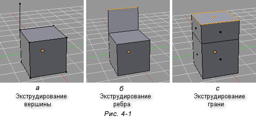
При выдавливании вершин существуют определенные закономерности формирования дополнительных элементов. Так если выдавливать несвязанные общим ребром вершины, то будут созданы только вершины и ребра. Если вершины лежат на одном ребре, то также появится новая грань.
При необходимости такое поведение можно изменить.
Если нажать Alt+E вместо E при выдавливании смежных вершин, то на экране появится контекстное меню Extrude. Выбор Extrude Vertices изменяет поведение по-умолчанию, когда выдавливание двух вершин, лежащих на одном ребре, приводит к появлению грани. В случае Exturde Vertices появятся только две новые вершины и два связующих ребра. Грани не будет.
Выдавливание внутрь (Inset Faces)
Кроме оригинального Extrude в Blender есть такой трансформатор как Inset (вставка, выдавливание во внутрь) Faces. В регионе инструментов он находится под Extrude. Горячая клавиша I. Его можно описать как нечто среднее между экструдированием и разделением грани инструментом Subdivide, который мы рассмотрим на следующем уроке.
С одной стороны, Inset Faces приводит к разделению исходных граней на более мелкие части, то же делает Subdivide. Однако то, как происходит «нарезка», схоже с Extrude. На рисунке ниже к треугольной и квадратной плоскостям применено вдавливание во внутрь. В первом случае образуется внутренняя треугольная грань, во втором – квадратная. Тоже самое происходит при Extrude, за исключением того, что в случае Extrude грань выдавливается наружу.
Практическая работа
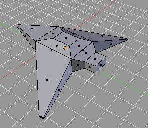
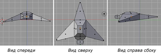
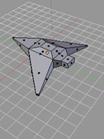
Создайте модель самолета.
Курс с инструкционными картами к части практических работ:
android-приложение, pdf-версия
Want to master Blender? Click here! and get our E-Book
Extruding in Blender is the most common modeling tool to help us shape and build geometry for our mesh object.
Extrude is an edit mode tool that pulls out new geometry from a selection in our mesh. We activate extrude by having a selection and pressing E to extrude those faces. Then move the mouse to change the depth of the extrude and left click to confirm the command.
In this article, we will cover the extrude tool and all its variations to model better and smarter with all the different variations of the extrude tools in Blender.
What is extrude and how to use it in Blender?
The extrude tool is an edit mode tool meant to extend a portion of our object. The most common use is with a mesh object by following these steps.
Instead of using the shortcut key, we can also use the toolbar.
Here, the gizmo will change to a line with a plus. The line shows the direction of the extrude. To use it, press the plus, hold, drag and release to confirm. Every time you press and drag, you perform a new extrusion on the selection.
Here, the extrude direction is diagonal since we selected both the top and side face, so the median direction becomes the extrusion direction showed by the gizmo.
We can access multiple variations of the extrude tool by pressing ALT+E while in edit mode or by pressing and holding on the extrude tool in the toolbar to bring up a menu showing the other variations.
These are the variations of the extrude tool:
The Extrude menu we bring up with ALT+E you see on the right side is slightly different. This is because this menu is context sensitive. We are currently in face select mode, so the options we have are for extruding faces. If we are in vertex select or edge, select we only see extrude vertices and/or extrude edges together with extrude repeat and spin.
Extrude repeat is the same as the basic extrude region. The difference is that we repeat the same extrusion several times. We can set the direction, number of times, and how far to extrude in the operator panel. We can find the operator panel in the lower left corner for the last operation or by pressing F9 on the keyboard to bring it up at the location of the mouse cursor.
The spin tool is its own separate tool in the toolbar. We can think of it as an extrude repeat with a spin around the location of the 3D cursor. We will cover the spin tool a bit later in this article, but we will start with the other extrude variations first.
With any of the variations of the extrude tool, or any of the modeling tools, there are slight differences between using the shortcut key and using the tool form the toolbar.
While using the tool from the toolbar, we click hold and release to confirm the operation. We then access any additional parameters for the command in the operator panel in the lower left corner or by hitting F9.
With the shortcut key, we press the key, move the mouse and then click to confirm. The difference is subtle, but many tools, including the extrude tools, give us options to change the behaviour of the tool before we click to confirm.
Now the extrude region tool doesn’t have any special options that work only for the extrude tool, but before we click to confirm, we can use the number pad or number row to set the exact distance we want to extrude.
We can also use the X, Y and Z key to extrude in one of these axis. Double tap any of them to use the local axis instead of the global and press Shift+X, Y or Z to omit the axis and constraint to the other two axis instead.
Here is an example.
This will extrude 0.1 meters in the global X direction.
Troubleshooting when the extrude tool is not working
Before we continue, also know that the extrude tool is a macro. That means that it uses multiple tools to create the operation. This means that we may end up performing half an extrude, and this is difficult to spot.
The most common way to perform half an extrude is to press E, followed by a right click. It looks like we cancelled the entire operation, but really we still created the geometry. We just canceled the last move operation. This leaves us with overlapping geometry.
To spot this problem, we need to enable face center points in the overlay menu.
Now, while we are in face select mode in edit mode, we will see a dot in the center of every face. If we see a dot in the middle of an edge, it means that we have hidden geometry there. This can cause a lot of problems later if we don’t solve it.
If we have this problem we can solve it by merging vertices by distance.
This will merge vertices that sit on top of each other and collapse any geometry that were supported by these vertices.
How to extrude along a curved surface evenly?
To extrude along a curved shape, select along the shape and press Alt+E. Use the Extrude faces along normal command from the menu. Move the mouse to change the extrude amount and click to confirm.
Let’s say that we have a curved object we want to extrude along, but we want the extrusion to follow the original shape rather than extruding in the same direction all the way. Here is an example. If we have this curved object shown in the image, and we press E to extrude the extrusion will go in a single direction.
We most clearly see the problem at the ends of the shape where the extrusion doesn’t align with the original shape. Instead, we can use extrude along normal to follow the original shape.
While in edit mode and using face selection, press Alt+E and choose extrude along normal and start to move the mouse to see the effect. In the image below, you can see how the ends align with the original shape.
Something to watch out for here is that we cannot extrude too far. If we do the faces, we extrude will overlap and we will have self intersecting geometry.
How to extrude in a circle in Blender?
To extrude a circle, we use the extrude along normal command. Select the circle, press Alt+E and choose Extrude faces along normal. Move the mouse until the extrusion is the desired depth and left click to confirm.
This example is like the previous one, where we extruded along a curved surface. What we usually see here is that we try to extrude using the regular extrude region command and we get an extrusion that looks like the image below.
The extrude along normal command instead takes the normal of each face and extrude along that instead of extruding all faces in the same direction as with the extrude region tool.
Extruding individual faces
If we have a selection that isn’t connected, each selected region is extruded individually, but if we have multiple faces next to each other and we want to extrude them individually, we use the extrude individual command.
Press Alt+E and choose extrude individual faces. Move the mouse until the extrusion reaches as far as you want and left click to confirm.
We won’t see a difference in solvid view, but if we press Shift+Z to toggle to wireframe view mode, you will see that we now have faces between the extruded faces. We can now continue to model each extrusion separately.
The faces in between extrusions are not internal faces, they just happen to exactly overlap with the walls of the adjacent extrusions. If we press G to move a single extruded face, it becomes clear that they are individually extruded.
If we set out transform pivot point to individual origins in the control options found in the center of the header of the 3D viewport, we can then press S to scale down the faces individually as an example.
How do you extrude inwards without leaving faces?
In edit mode, press Alt+E and choose Extrude manifold. Move your mouse to change the depth of the extrusion and left-click to confirm.
Here is an example of where this is useful. Let’s say that we have a subdivided cube and we want to extrude a corener downwards. Here is what we get using trhe regular extrude tool.
The extrude manifold tool will help us remove any zero area faces and connect the newly extruded face to the quads on the side, creating n-gons with 5 vertices.
This tool works great when we have simple shapes but keep in mind that the tool is quite new, only introduced in version 2.9x and geometry may not connect ideally in all cases.
How do you extrude freely using the cursor in Blender?
In edit mode, select the elements you want to extrude, hold Ctrl and left click to where you want to extrude.
The extrusion we create will go straight from the selection to the mouse cursor position according to the view. In the example image above, I went to top orthographic view by pressing 7 on the number pad. In most cases you want to be in one of the orthographic views, top, front or right view. It is easy to end up with overlapping geometry and angles that can be hard to spot in user perspective.
How do you rotate and extrude in Blender?
To both rotate and extrude, we don’t use the extrude tool. Instead, we use the spin tool.
Follow these steps to use the spin tool:
We can further adjust the spin by adjusting the parameters in the opertaor panel
The steps setting will decide how many extrusions the spin will use. If we check «use duplicates» the extrusion will only generate a copy of the selection without creating geometry between each step.
The angle setting is how many degrees we want to spin around and if we go a full circle, we can check auto merge to have the first and last element merge together.
The center X, Y, and Z values will move the point we spin around while the axis X, Y and Z will rotate the center point so that the spin is twisted in multiple or a different direction.
Final thoughts
The extrude tool is one of the most common tools we use in 3D modeling. It is an excellent way to extend and add geometry that is versatile. In Blender we can use it in two ways. Both through the tools panel and the shortcut key with slight variation in functionality.
There are other areas in Blender where we can extrude as well. For instance curves and grease pencil strokes. But if you understand how to use the extrude tool for mesh objects you understand how to extrude in all parts of Blender where it is applicable.
Extrude RegionпѓЃ
Toolbar ‣ Extrude Region
Extrusion tools duplicate vertices, while keeping the new geometry connected with the original vertices. Vertices are turned into edges and edges will form faces.
Single vertex extruded. пѓЃ
Single edge extruded. пѓЃ
This tool is of paramount importance for creating new geometry. It allows you to create parallelepipeds from rectangles and cylinders from circles, as well as easily creating such things as tree limbs.
The extrude tools differentiate in how the new geometry is connected in itself.
Only the border loop gets extruded. The inner region of the selection gets moved unchanged with the extrusion.
DetailsпѓЃ
Although the process is quite intuitive, the principles behind Extrude are fairly elaborate as discussed below:
First, the algorithm determines the outside edge loop of the extrude; that is, which among the selected edges will be changed into faces. By default (see below), the algorithm considers edges belonging to two or more selected faces as internal, and hence not part of the loop.
The edges in the edge loop are then changed into faces.
If the edges in the edge loop belong to only one face in the complete mesh, then all of the selected faces are duplicated and linked to the newly created faces. For example, rectangles will result in parallelepipeds during this stage.
In other cases, the selected faces are linked to the newly created faces but not duplicated. This prevents undesired faces from being retained “inside” the resulting mesh. This distinction is extremely important since it ensures the construction of consistently coherent, closed volumes at all times when using Extrude.
When extruding completely closed volumes (like e.g. a cube with all its six faces), extrusion results merely in a duplication, as the volume is duplicated, without any link to the original one.
Edges not belonging to selected faces, which form an “open” edge loop, are duplicated and a new face is created between the new edge and the original one.
Single selected vertices which do not belong to selected edges are duplicated and a new edge is created between the two.
© Copyright : This page is licensed under a CC-BY-SA 4.0 Int. License. Last updated on 08/14/2022.
ExtrudeпѓЃ
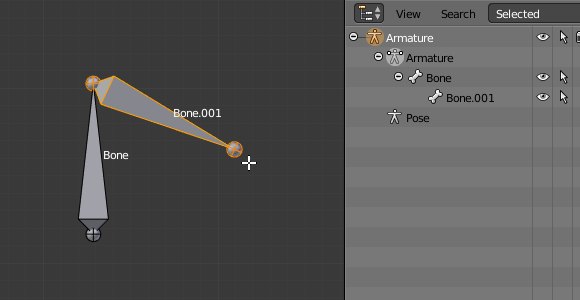
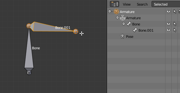
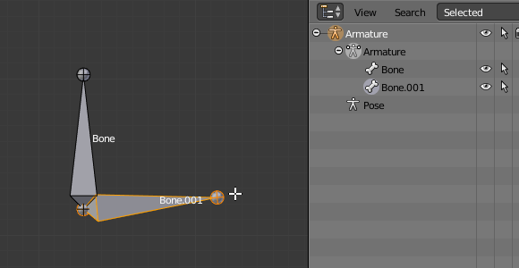
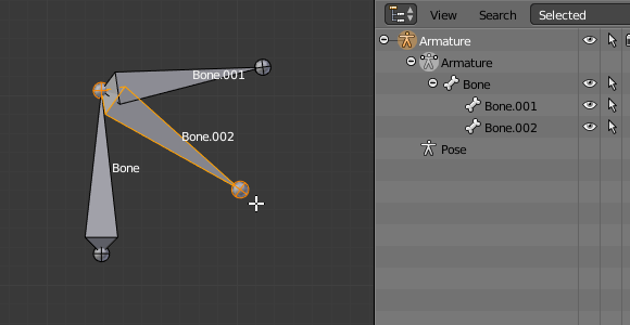
Armature ‣ Extrude
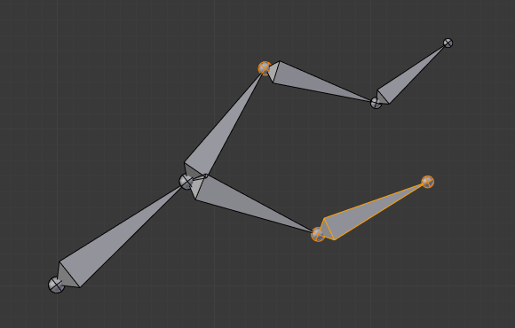 An armature with three selected tips. пѓЃ | 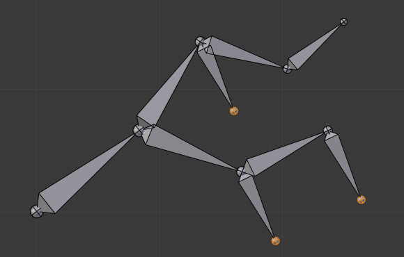 The three extruded bones. пѓЃ You also can use the rotating/scaling extrusions, as with meshes, by pressing respectively E R and E S – as well as locked extrusion along a global or local axis.
|
 Урок из серии: «Создание трехмерной графики в программе Blender»
