Date and time change made by rtc
Date and time change made by rtc
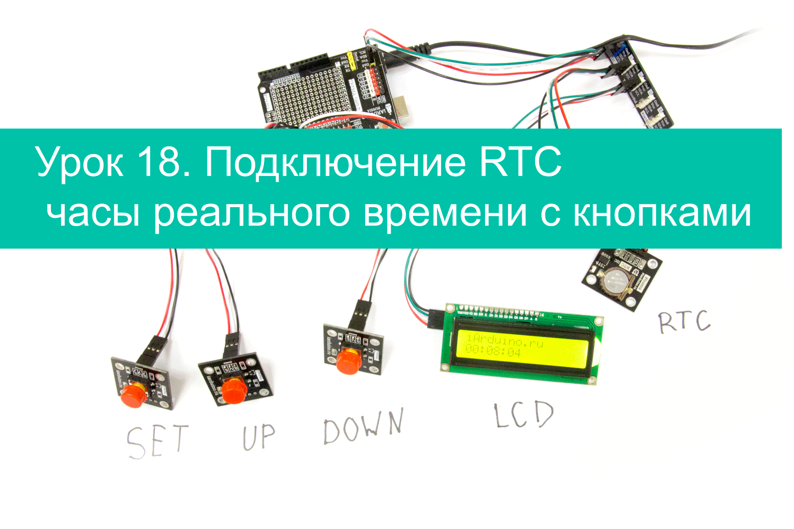
Урок 18. Подключение RTC часы реального времени с кнопками
В этом уроке мы научимся не только выводить, но и устанавливать время RTC модуля при помощи трёх кнопок.
Нам понадобится:
Для реализации проекта нам необходимо установить библиотеки:
Видео
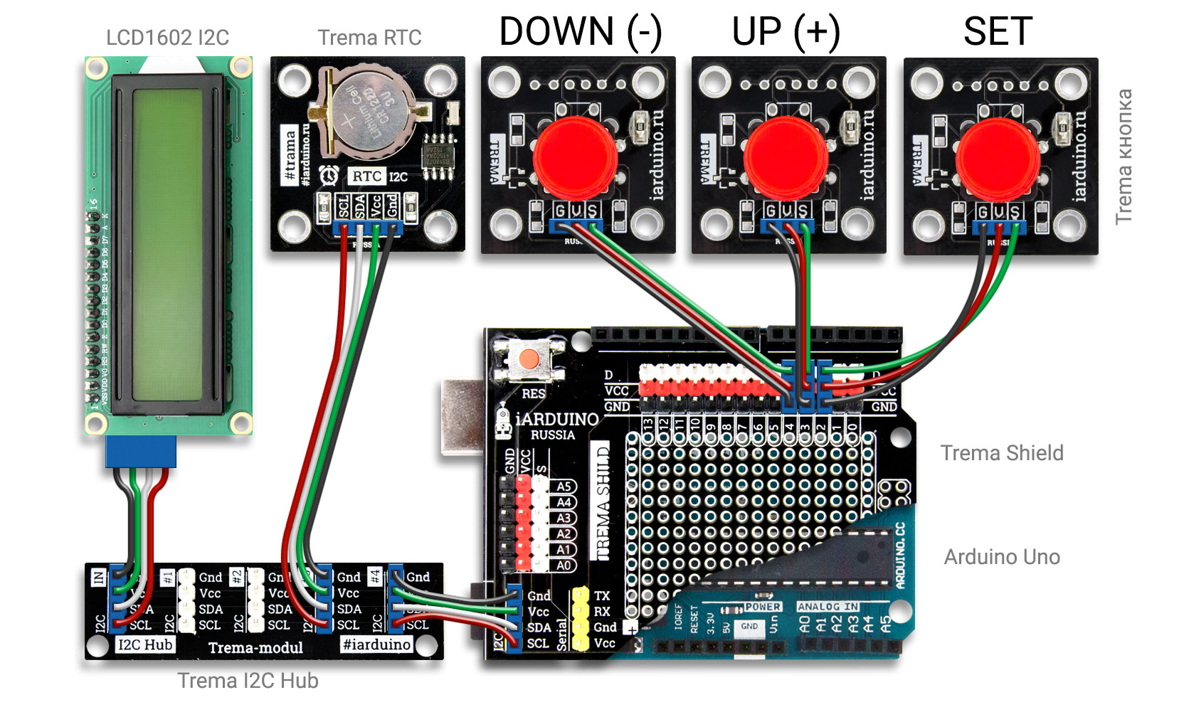
Схема подключения:
Подключение модулей RTC и LCD, данного урока, осуществляется к аппаратным выводам SDA, и SCL.
| RTC модуль Trema на базе чипа DS1307 / LCD дисплей на базе чипа LCD1602 | Arduino Uno |
|---|---|
| GND | GND |
| Vcc | +5V |
| SDA (Serial DAta) | A4 |
| SCL (Serial CLock) | A5 |
подключение кнопок: кнопка «SET» к выводу 2, кнопка «UP» к выводу 3 и копка «DOWN» к выводу 4.
Код программы:
При подключении библиотеки «iarduino_RTC» нужно указать, с каким модулем ей работать, в данном случае это модуль Trema на базе чипа DS1307:
Аналогичный алгоритм действий при подключении библиотеки «LiquidCrystal_I2C» для работы с LCD дисплеем LCD1602 IIC/I2C(синий) или LCD1602 IIC/I2C(зелёный) :
В библиотеке «iarduino_RTC» доступны 9 числовых переменных: seconds, minutes, hours, Hours, midday, day, weekday, month и year, значения которых обновляются после каждого вызова функции gettime(). Эти переменные мы будим использовать для изменения даты и времени.
Алгоритм работы кнопок следующий:
Как использовать RTC (часы реального времени) с Arduino и LCD
В данной статье мы рассмотрим, как сделать точные часы на базе Arduino или AVR-микроконтроллера микросхемы часов реального времени DS1307. Время будет выводиться на LCD дисплей.
Что необходимо
Вы можете заменить плату Arduino на контроллер Atmel, но убедитесь, что у него достаточно входных и выходных выводов и есть аппаратная реализация интерфейса I2C. Я использую ATMega168A-PU. Если вы будете использовать отдельный микроконтроллер, то вам понадобится программатор, например, AVR MKII ISP.
Предполагается, что читатель знаком с макетированием, программированием в Arduino IDE и имеет некоторые знания языка программирования C. Обе программы, приведенные ниже, не нуждаются в дополнительном разъяснении.
Введение
Вот здесь и будет удобно использование микросхемы RTC (Real Time Clock, часов реального времени). Эта микросхема с батарейкой 3В или каким-либо другим источником питания следит за временем и датой. Часы/календарь обеспечивают информацию о секундах, минутах, часах, дне недели, дате, месяце и годе. Микросхема корректно работает с месяцами продолжительностью 30/31 день и с високосными годами. Связь осуществляется через шину I2C (шина I2C в данной статье не обсуждается).
Если напряжение на главной шине питания Vcc падает ниже напряжения на батарее Vbat, RTC автоматически переключается в режим низкого энергопотребления от резервной батареи. Резервная батарея – это обычно миниатюрная батарея (в виде «монетки», «таблетки») напряжением 3 вольта, подключенная между выводом 3 и корпусом. Таким образом, микросхема по-прежнему будет следить за временем и датой, и когда на основную схему будет подано питание, микроконтроллер получит текущие время и дату.
В этом проекте мы будем использовать DS1307. У этой микросхемы вывод 7 является выводом SQW/OUT (выходом прямоугольных импульсов). Вы можете использовать этот вывод для мигания светодиодом и оповещения микроконтроллера о необходимости фиксации времени. Мы будем делать и то, и другое. Ниже приведено объяснение работы с выводом SQW/OUT.
Для управления работой вывода SQW/OUT используется регистр управления DS1307.
| Бит 7 | Бит 6 | Бит 5 | Бит 4 | Бит 3 | Бит 2 | Бит 1 | Бит 0 |
|---|---|---|---|---|---|---|---|
| OUT | 0 | 0 | SQWE | 0 | 0 | RS1 | RS0 |
Бит 7: управление выходом (OUT) Этот бит управляет выходным уровнем вывода SQW/OUT, когда выход прямоугольных импульсов выключен. Если SQWE = 0, логический уровень на выводе SQW/OUT равен 1, если OUT = 1, и 0, если OUT = 0. Первоначально обычно этот бит равен 0. Бит 4: включение прямоугольных импульсов (SQWE) Этот бит, когда установлен в логическую 1, включает выходной генератор. Частота прямоугольных импульсов зависит от значений битов RS0 и RS1. Когда частота прямоугольных импульсов настроена на значение 1 Гц, часовые регистры обновляются во время спада прямоугольного импульса. Первоначально обычно этот бит равен 0. Биты 1 и 0: выбор частоты (RS[1:0]) Эти биты управляют частотой выходных прямоугольных импульсов, когда выход прямоугольных импульсов включен. Следующая таблица перечисляет частоты прямоугольных импульсов, которые могут быть выбраны с помощью данных битов. Первоначально обычно эти биты равны 1.
| RS1 | RS0 | Частота импульсов и уровень на выходе SQW/OUT | SQWE | OUT |
|---|---|---|---|---|
| 0 | 0 | 1 Гц | 1 | x |
| 0 | 1 | 4,096 кГц | 1 | x |
| 1 | 0 | 8,192 кГц | 1 | x |
| 1 | 1 | 32,768 кГц | 1 | x |
| x | x | 0 | 0 | 0 |
| x | x | 1 | 0 | 1 |
Данная таблица поможет вам с частотой:
| Частота импульсов | Бит 7 | Бит 6 | Бит 5 | Бит 4 | Бит 3 | Бит 2 | Бит 1 | Бит 0 |
|---|---|---|---|---|---|---|---|---|
| 1 Гц | 0 | 0 | 0 | 1 | 0 | 0 | 0 | 0 |
| 4,096 кГц | 0 | 0 | 0 | 1 | 0 | 0 | 0 | 1 |
| 8,192 кГц | 0 | 0 | 0 | 1 | 0 | 0 | 1 | 0 |
| 32,768 кГц | 0 | 0 | 0 | 1 | 0 | 0 | 1 | 1 |
Если вы подключили светодиод и резистор к выводу 7 и хотите, чтобы светодиод мигал с частотой 1 Гц, то должны записать в регистр управления значение 0b00010000. Если вам нужны импульсы 4,096 кГц, то вы должны записать 0b000100001. В этом случае, чтобы увидеть импульсы вам понадобится осциллограф, так как светодиод будет мигать так быстро, что будет казаться, что он светится постоянно. Мы будем использовать импульсы с частотой 1 Гц.
Аппаратная часть
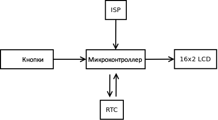
Ниже показана структурная схема того, что нам необходимо.
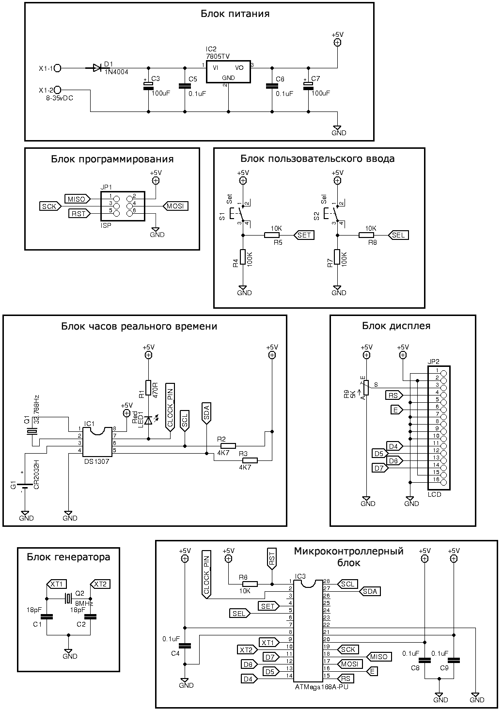
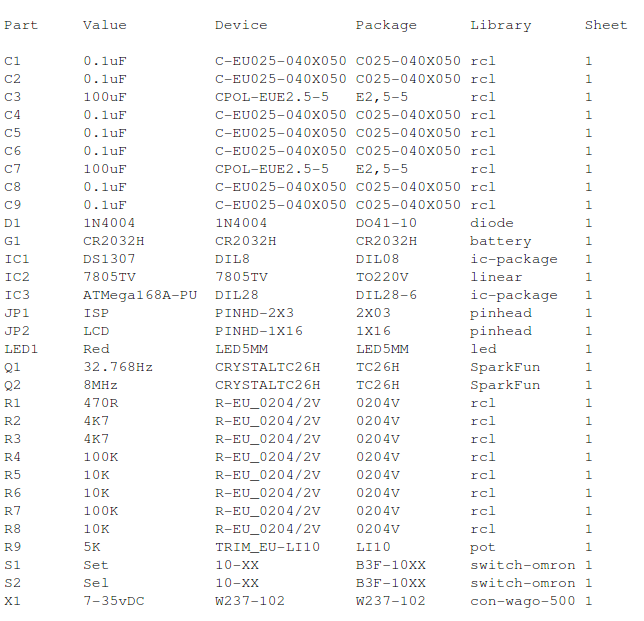
Перечень элементов
Ниже приведен скриншот из Eagle:
Программное обеспечение
В этом руководстве мы будем использовать два различных скетча: один, который записывает время и дату в RTC, и один, который считывает время и дату из RTC. Мы сделали так потому, что так вы сможете получить более полное представление о том, что происходит. Мы будем использовать одну и ту же схему для обеих программ.
Сперва мы запишем время и дату в RTC, что аналогично установке времени на часах.
Мы используем две кнопки. Одну для увеличения часов, минут, даты, месяца, года и дня недели, а вторую для выбора между ними. Приложение не считывает состояния каких-либо критически важных датчиков, поэтому мы будем использовать прерывания для проверки, нажата ли кнопка, и обработки дребезга контактов.
Следующий код устанавливает значения и записывает их в RTC:
Эта программа начинается с короткого приветственного сообщения. Это сообщение говорит нам, что подано питание, LCD работает, и что программа запустилась. Так как скетч служит лишь для того, чтобы показать, как записать данные из Arduino в RTC DS1307, то в нем отсутствует вспомогательный функционал (проверка, попадают ли значения в допустимые диапазоны; зацикливание при нажимании на кнопку увеличения значения, то есть сброс на 0, когда значение, например, минут превысит 60, и т.д.)
Заключение
В данной статье мы рассмотрели микросхему DS1307 от Maxim Integrated и написали две демонстрационные программы: одну для установки времени и даты и вторую для чтения времени и даты. Для проверки нажатия кнопок мы использовали прерывания, в которых также избавлялись от влияния дребезга контактов.
Фото и видео
Установка времени
Считывание времени
Interface DS1307 RTC Module with Arduino – Display Date/Time on OLED
In this tutorial, we will learn to interface a DS1307 RTC module. Firstly, we will look into these questions; What is RTC (Real-time clock)? Why a real-time clock is used? How an RTC module communicate with Arduino on an I2C communication bus? How to make a digital clock using Arduino and DS1307 RTC module? Secondly, we will discuss pinout, pin configuration details, interfacing circuit with Arduino, and example code at the end.
Pre-Requisites
Table of Contents
What is RTC or Real time Clock?
As its name suggests, a real-time clock is used to keep a record of the time and to display time. It is used in many digital electronic devices like computers, digital smartwatches, data loggers, and situations where you need to keep track of time. one of the great benefits of a real-time clock is that it also keeps a record of time even if the power supply is not available.
Now the question is how can an electronics device like real-time clockwork without the use of a power supply. Because almost all RTC modules come with small coin size 20mm 3V lithium coin cells which can work for years. Usually, CR2032 coil cells are used.
DS1307 RTC IC
At the center of the DS1307 RTC module is an 8-pin DS1307 chip. It provides a real-time clock that is used to keep track of seconds, minutes, hours, days, months, and years. It uses the I2C communication protocol for communicating with other devices like in our case we are using Arduino. Arduino read values of time and date from DS1307 using the I2C communication protocol. Moreover, It also has a feature to keep a record of the exact time in case of power failure with the help of a backup battery. It is used to make a real-time clock using some other electronic components.
DS1307 Chip Pinout
The following figure shows the pinout diagram of DS1307 IC.
If you want to use this IC directly with Arduino, you need to use external components to connect with DS1307. The following circuit diagram shows the connections of all required components with DS1306:
real time clock DS1307 circuit diagram
» data-medium-file=https://microcontrollerslab.com/wp-content/uploads/2014/11/real-time-clock-DS1307-circuit-diagram-300×226.png data-large-file=https://microcontrollerslab.com/wp-content/uploads/2014/11/real-time-clock-DS1307-circuit-diagram.png loading=lazy width=731 height=551 svg+xml,%3Csvg%20xmlns=%22http://www.w3.org/2000/svg%22%20width=%22731%22%20height=%22551%22%3E%3C/svg%3E» alt=»real time clock DS1307 circuit diagram» data-ezsrcset=»https://microcontrollerslab.com/wp-content/uploads/2014/11/real-time-clock-DS1307-circuit-diagram.png 731w,https://microcontrollerslab.com/wp-content/uploads/2014/11/real-time-clock-DS1307-circuit-diagram-200×151.png 200w,https://microcontrollerslab.com/wp-content/uploads/2014/11/real-time-clock-DS1307-circuit-diagram-300×226.png 300w,https://microcontrollerslab.com/wp-content/uploads/2014/11/real-time-clock-DS1307-circuit-diagram-80×60.png 80w,https://microcontrollerslab.com/wp-content/uploads/2014/11/real-time-clock-DS1307-circuit-diagram-220×166.png 220w,https://microcontrollerslab.com/wp-content/uploads/2014/11/real-time-clock-DS1307-circuit-diagram-133×100.png 133w,https://microcontrollerslab.com/wp-content/uploads/2014/11/real-time-clock-DS1307-circuit-diagram-199×150.png 199w,https://microcontrollerslab.com/wp-content/uploads/2014/11/real-time-clock-DS1307-circuit-diagram-316×238.png 316w,https://microcontrollerslab.com/wp-content/uploads/2014/11/real-time-clock-DS1307-circuit-diagram-551×415.png 551w,https://microcontrollerslab.com/wp-content/uploads/2014/11/real-time-clock-DS1307-circuit-diagram-646×487.png 646w» sizes=»(max-width: 731px) 100vw, 731px» ezimgfmt=»rs rscb1 src ng ngcb1 srcset» data-ezsrc=https://microcontrollerslab.com/wp-content/uploads/2014/11/real-time-clock-DS1307-circuit-diagram.png> Real Time Clock DS1307 Circuit Diagram
But instead of using DS1307 chip alone and making your own PCB desing, you can get a ready to use DS1307 RTC module in very low cost.
DS1307 RTC Module
DS1307 RTC module has all onboard components which are required for the correct functionality of a DS3107 chip. On top of that, it contains a holder to connect a 20mm 3V lithium coin cell. This holder can contain any CR2032 battery. Now let’s discuss the components of this module one by one:
At the center of the DS1307 RTC module is a chip which we have discussed earlier. This chip keeps track of seconds, minutes, hours, days, and months. At the end of every month, this chip automatically adjusts its seconds:minutes: hours, and date. It is also possible to configure time display in 12-hour with an AM and PM or 24-hour format.
32kHz Crystal Oscillator
As discussed earlier, the DS1307 chip requires 32KHz of an external crystal oscillator for its operation ( time-keeping). Therefore, the RTC module comes with 32KHz of an external crystal oscillator.
But there is one problem with this 32KHz crystal oscillator that is a change in environmental temperature affects the oscillation frequency of the crystal oscillator. This change in 32KHz of external crystal oscillation frequency is negligible. But it shows an error in the long run. It gives a clock drift of 2-3 minutes per month.
Onboard 24C32 EEPROM
DS1307 RTC module also contains onboard 24C32 EEPROM. This EEPROM can store 32 bytes and have limited read-write operations. We can use this memory to save time when we want to use an RTC module for Alarm based projects. For example, we want to set an alarm at 8:00 AM every day. We can save this time value into EEPROM and whenever the time matches with this saved value, an alarm starts.
These EEPROM chips also communicate with microcontrollers or Arduino over the I2C bus. Hence, it shares the same I2C bus as DS1307. Different slave addresses are assigned to EEPROM (o 0x50 Hex) and DS1307 chip to communicate with them on the same I2C bus.
Backup Battery
On the back side of a RTC module, there is a holder to connect CR2032 coil cell. This backup battery is used to keep track of time accurate even when the main power source which connected to DS1307 fails. This chip contains a power sensing circutry which senses main power and whenever the main power shutdown, it swithces to the backup coil cell.
In backup mode, DS1307 consumes only 300nA current. That means a backup battery based on a coin cell can work for more than 17 years. Because, generally, the capacity of CR2032 battery is 47mAh and chip consumes only 300nA when powers through a battery.
Life_time = 47mAh/300nA = 156666 hours = 6527 days = 17+ years
DS18B20 Sensor
There is an empty slot available on this module to connect an external DS18B20 digital thermometer. The three empty pinouts in the bottom right corner is a place holder for the DS18B20 sensor and output of the sensor can be received from DS pin of RTC module.
DS1307 RTC Module Pinout
The following figure shows the pinout diagram. This module exposes a total of 7 pins out of which two are power supply pins and two are for SCL and SDA pins for the I2C communication bus. We have already seen the functionality of all these pins in the previous sections.
DS1307 and Arduino Wiring Diagram
First make connections with DS1307 RTC module and Arduino according to this connection diagram:
| Arduino UNO | DS1307 RTC Module |
|---|---|
| 5V | VCC |
| GND | GND |
| A4 | SDA |
| A5 | SCL |
Install DS1307 Library In Arduino IDE
But it demands an exercise to write a code from scratch. Luckily, an Arduino RTClib library is available, which implements callback functions to get time measurements from an RTC module. This library hides all the complexity to interact with an RTC module over I2C communication. We can use simple callback functions implemented by RTClib to read data from DS1307.
Therefore, to program a DS1307 RTC module with Arduino, you will use the RTClib library available in Arduino IDE.
To apply this library, first, we need to install this library in Arduino IDE by going to Arduino’s library manager. Open Arduino IDE, go to Tools > Manage Libraries.
After that, this window library manager window will appear. Search for “RTClib” by typing in the search bar. You will see many options for DS1307. But the one that we will use in this tutorial is RTClib by Adafruit. Select RTClib by Adafruit and click on the install button.
When you click on the install button, you may get a message that RTClib may require other libraries dependencies which is currently not installed in your Arduino IDE. We recommend you to install all dependencies by clicking on install button. Otherwise, RTClib will not work properly.
Arduino Code
OLED with DS1307 and Arduino
Now if you want to display time and data on OLED display, make connections according to this diagram. Connect SSD1306 OLED with the same I2C bus.
Arduino Code OLED and DS1307
Make sure to install Adafruit SSD1306 OLED library in Arduino IDE by going to Tools > Library Manager.
DS1307 Proteus Simulation
In this section, we will see a proteus simulation of DS1307 RTC module by using all external components and display the value of time and data on 16×2 LCD.
If you don’t know how to use 16×2 LCD with Arduin, you can read this articles:
Proteus Circuit
The following circuit shows the connections of DS1307chip along with external components with an Arduino. SCL and SDA pins of DS1307 are connected with SCL and SDA pins of Arduino. If you have already gone through the above-mentioned article on LCD interfacing with Arduino and other basic articles to get a know-how of Arduino, you can easily understand the following circuit.
circuit diagram of DIgital clock using real time clock and Arduino
Arduino Code
This Arduino sketch displays the time and date value on 16×2 LCD.
The result of above code is given below:
circuit diagram of DIgital clock using real time clock and Arduino result
Настройка модуля часов реального времени RTC для Arduino
Все, что вам нужно сделать, так это сконфигурировать RTC-чип в соответствии с текущей датой и временем … и сегодняшний проект поможет вам это сделать!
Проект
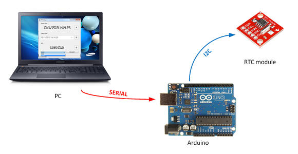
RTCSetup состоит из двух элементов:
Графический интерфейс пользователя и скетч соединены по последовательному интерфейсу с помощью несложного протокола. Исходный код для них доступен в моем хранилище данных Github.
Arduino и часы реального времени
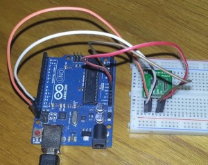
Для связи с чипом DS1307 я выбрал библиотеку RTClib хранилища Adafruit. Данный чип наиболее часто используется в модулях RTC энтузиастами со всего мира. Соединение между ИС и Arduino устанавливается с помощью шины I2C:
На рисунке показано соединение, организованное с помощью “новых” выводов I2C платы Arduino Uno; естественно вы можете использовать выводы A4 и A5.
Скетч Arduino получает команды от ПК, выполняет их и посылает назад ответный сигнал.
Протокол
Как я указал ранее, для связи между графическим интерфейсом пользователя и Arduino используется несложный протокол, созданный с помощью только 4-х команд:
Команда: ##
Первая команда, отправленная после установления соединения, используется ПК для подтверждения “совместимости” модуля, подключенного к последовательному порту. Arduino должен ответить командой «!!«
Команда: ?V
Данная команда используется для получения версии скетча. Arduino отвечает строковым параметром, определенным как константа в начале скетча:
#define VERSION «1.0»
Команда: ?T
Данная команда, используемая для получения фактической даты и времени, считывается из модуля RTC. Плата Arduino отвечает строковым параметром в формате: dd/MM/yyyy hh:mm:ss.
Команда: !TddMMyyyyhhmmss
Данная команда используется для установки времени RTC. Arduino отвечает командой «OK».
Графический интерфейс пользователя (GUI)
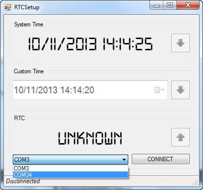
Графический интерфейс пользователя, разработанный на C#, общается с Arduino по вышеуказанному протоколу и выполняет три функции:
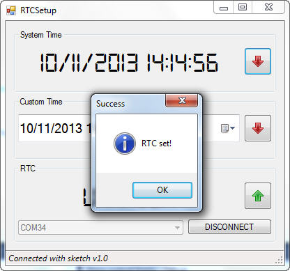
В первом окне будет показано фактическое время ПК. После нажатия правой кнопки мыши (на красной стрелке) вы сможете сконфигурировать модуль RTC с данным временем :
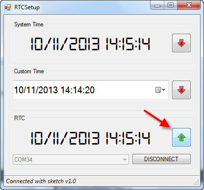
С помощью кнопки с зеленой стрелкой вы сможете получить фактическое время, хранимое в модуле RTC:
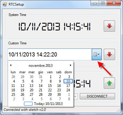
И, наконец, с помощью выпадающего списка даты в центре, вы сможете выбрать требуемое значение даты и времени, и затем отправить эти значения в модуль RTC:
Технические данные
Я использовал метод, описанный в данном учебном руководстве, для внедрения пользовательского шрифта в приложение.
Arduino RTC Tutorial: Using DS1307 RTC with Arduino
Do you want to maintain hours, minutes, and seconds, as well as, day, month, and year information for your Arduino Project? Well then using an RTC (Real Time Clock), will be for you!
Through this blog, you will learn how to use the DS1307 RTC module with your Arduino in a few steps!
Today’s blog will cover:
What is an RTC (Real Time Clock), why do we need RTC for Arduino microcontroller?
An RTC (real-time clock) refers to a clock that tracks the current time and can be used to program actions at a specific time.
Arduino and almost all microcontrollers have built-in timers, they can run as long as there is power. However, once the power is turned off (either manually or due to a power failure), all timers will be reset to 0.
It is acceptable to use the internal timer for timing for simple projects if you don’t mind when the timer resets to zero once there is no power. But for projects such as data loggers, clocks, alarms, which requires the timer to run independently of the external power supply, you need to use an RTC.
Almost all RTC are low-current built-in ICs and able to run on a single lithium battery for many years. Currently, RTC based on the DS1307 real-time clock is one of the most popular RTC modules.
What is a DS1307 RTC?
Grove – RTC ($6.90)
We also offer a similar product: Grove – High Precision RTC. Compared to the Grove-RTC, this module can provide a more accurate result and provide a programmable clock output for peripheral devices as well as minute and half minute interrupt.
Without further ado let us jump right into the tutorial on how to use the DS1307 RTC with Arduino
Tutorial: Using DS1307 RTC with Arduino
Through this tutorial, you will learn how to use the DS1307 RTC with your Arduino in a few simple steps.
What do you need?
Step by step instructions using the RTC with your Arduino
Step 1: Connecting the Hardware
Step 2: Using Software
That’s all on how to use the DS1307 with the Arduino! Want to do more with RTC with Arduino? Here are some RTC Arduino project ideas to get you started!
RTC Arduino Project Ideas
RTC Arduino Real-Time Garden Watering System
Tired of your plants dying because you forgot to water them or just lazy to water your plants? Why not try this automated plant watering project to save your plants today with the a RTC!
What do you need?
Interested? You can check out the full tutorial by Maximilian Dullo on Arduino Project Hub!
Compact Alarm with Card Reader and RTC
With this alarm, you can tell whenever someone enters your house which can be turned on and off with a card reader and also automatically activated with the RTC!
What do you need?
Interested? You can check out the full tutorial by Simonee Adobs on Arduino Project Hub here!
OLED RTC Clock
With an RTC module, you can of course also make your OLED digital clock with the Arduino which shows the date, time and day!
What do you need
Interested? You can find the full tutorial on Simple Projects!
Summary
That’s all on Arduino Tutorial: Using DS1307 RTC with Arduino! With the DS1307 RTC, you can now keep time and make awesome projects that involve data-loggers or clocks! As long as your project requires consistent timekeeping, using an RTC module would be the way to go.
If you have any questions regarding this tutorial or DS1307 Grove RTC, do leave them down in the comments section down below!
