How to draw latex
How to draw latex
How to draw Vector Graphics using TikZ in LaTeX
Author: Cody Herring (May 2013)
Procedural graphics in LaTeX: the basics
Traditionally, graphics are represented as bitmaps, with anything from 1 bit (black and white) to 24 bits (true color). This allows for simple display of graphics on a traditional (rectangular) computer screen. However, it can be difficult and tedious to generate bitmaps that accurately represent what should be shown on a document or on paper.
Procedural graphics help with this by allowing for a more well-defined and easily understood system such as Scalable Vector Graphics (SVG) to be used. By defining vectors, lines, and shapes rather than individual pixels, images can easily be generated for multiple sizes, aspect ratios, pixel densities, printing qualities, and more. This tutorial will provide a brief introduction into procedural graphics using Portable Graphics Format and TikZ:
Extensive documentation on TikZ and PGF can be found in the PGF Manual.
Using PGF and TikZ
In order to use the TikZ package, it must be imported:
In order to draw pictures, the tikzpicture environment must be used:
Basic drawing
TikZ allows for many different shapes and paths to be drawn. Here some basic drawing techniques will be shown. These techniques can be combined to form more complex drawings.
Straight paths
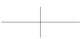
A straight path from one point to another can be drawn with the \draw command according to an X/Y (horizontal/vertical) coordinate system, like so:
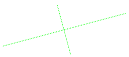
Styles can be applied to these lines by adding additional parameters. Here’s the same diagram, but with green, dotted, ultra thick lines rotated 15 degrees counterclockwise:
Changing the size of a diagram
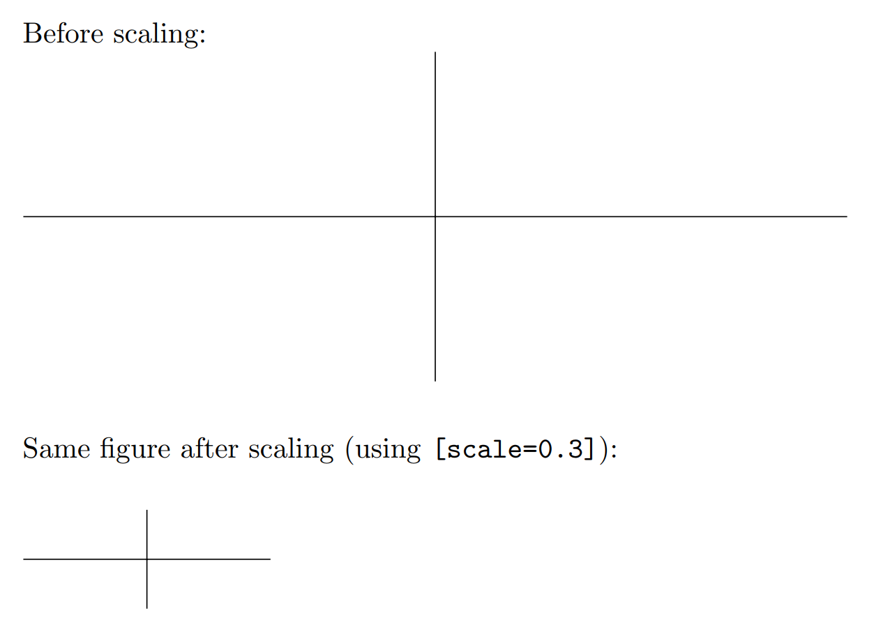
Sometimes the default size of a diagram is too large or too small. Using the scale parameter when declaring the tikzpicture environment allows for different sizes while maintaining the same proportions:
The following image shows the before and after effect of applying [scale=0.3] :
Adding arrow tips
Arrows can be useful for graphs and diagrams, and they’re simple to include in a TikZ picture. The styles demonstrated previously may be used, as well as several different arrow tips.
Drawing curves
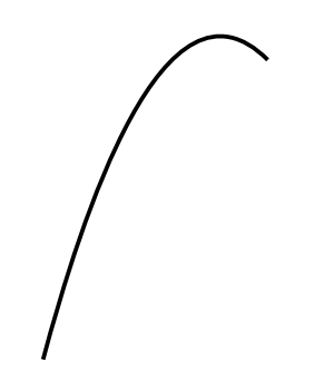
The simplest way to draw a curve with TikZ is by specifying the start and end point, and the desired angle leaving the start point and arriving at the end point.
Much more complex diagrams can also be created using chained calls. PGF will attempt to draw the smoothest lines possible using the directions provided.
Conclusion
There’s no end to what can be drawn with vector graphics, and their value in allowing for scalable, easily editable diagrams and pictures is a boon to LaTeX users looking for an easy way to use graphics. This post is scratching the surface of what is possible, but should be a good introduction to the capabilities of vector graphics and the TikZ/PGF environment.
TikZ package
Contents
Introduction
Firstly, load the tikz package by including the line \usepackage
This example produces the following output:
It’s important to notice the semicolon ; used at the end of each draw command.
Note: The tikzfigure environment can be enclosed inside a figure or similar environment. See the Inserting Images article for more information on this topic.
Basic elements: points, lines and paths
In this section we provide some examples showing how to create some basic graphic elements which can be combined to create more elaborate figures.
This example produces the following output:
There are three basic commands in this example:
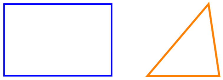
Basic geometric shapes: Circles, ellipses and polygons
Geometric figures can be constructed from simpler elements so let’s start with circles, ellipses and arcs.
This example produces the following output:
In addition to curved geometric shapes you can also create elements that use straight lines, using a similar syntax:
This example produces the following output:
Diagrams
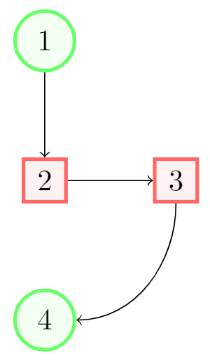
Nodes are probably the most versatile elements in TikZ. We’ve already used one node in the introduction—to add some text to the figure. The next example uses nodes to create a diagram.
This example produces the following output:
There are essentially three commands in this figure: A node definition, a node declaration and lines that join two nodes.
Reference Guide
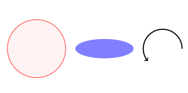
Possible color and thickness parameters in the tikz package:
| parameter | values | picture |
|---|---|---|
| color | white, black, red, green, blue, cyan, magenta, yellow | 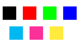 |
| thickness | ultra thin, very thin, thin, thick, very thick, ultra thick | 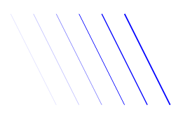 |
More colours may be available in your L a T e X distribution. See Using colours in LaTeX
Step-by-Step Tutorials about How to Draw Illustrations in LaTeX
Examples are From Mathematics, Physics and Engineering
Tutorials
Choose your technical area and discover step-by-step tutorials:
Mathematics
Physics
Engineering
Economics
Computer Science
Chemistry
Fun Learning Activities
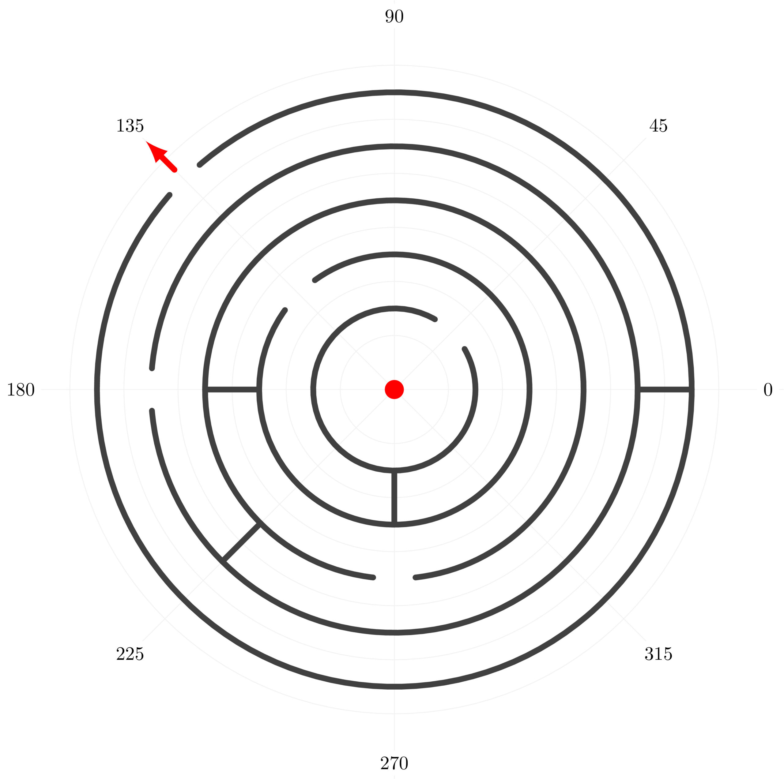
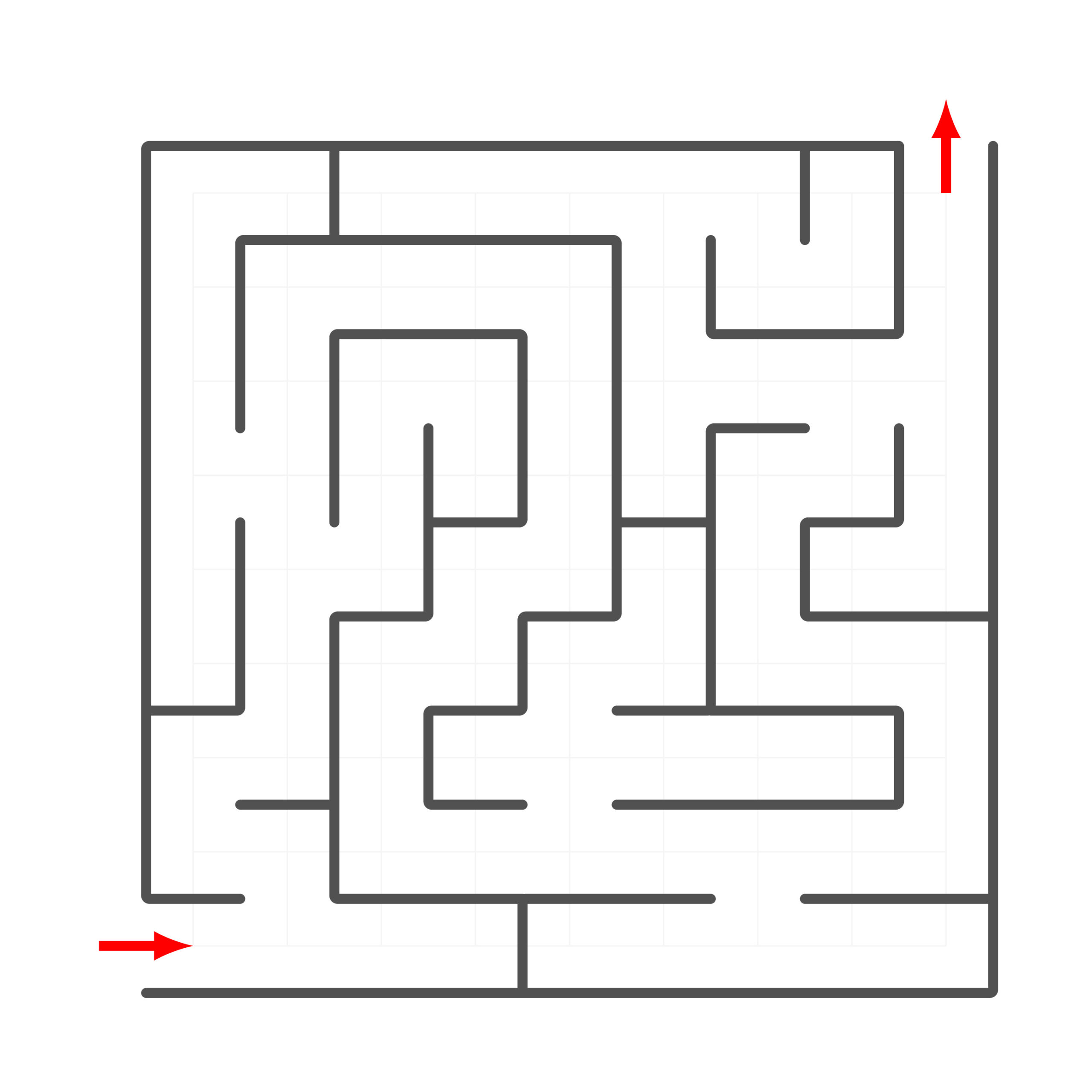
To make the learning process appealing, we create fun activities from time to time. This includes solving mazes, puzzles and quizzes!
Circular TikZ Maze
Standard TikZ Maze
TikZ for Beginners Course is Live!
The course is an introduction to TikZ package which is dedicated to beginners. It has 9 lessons and each one has tasks and one big challenge. To cite few, the latter corresponds to:
Each challenge has a purpose, for example: solving a maze teaches you how to draw straight lines between points defined by cartesian coordinates (lesson 2).
How to Draw Flowcharts in LaTeX using TikZ?
What is a Flowchart?
Common Elements of a Flowchart
There are different types of building blocks representing different elements in a flowchart:
Process Block
It represents an operation that changes system data. It has a rectangular shape.
Decision Block
It is used to show any kind of conditional operation that divides our flow path into two. It has a rhombus (diamond) shape.
Input/Output Block
It indicates the process of reading or writing. It’s usually used for external data input or printing data to a display. It is represented as a rhomboid.
Predefined Process Block
It is used for calls made to known, defined processes. It is shown as a rectangle with double-struck vertical edges.
Terminal Block
It represents the beginning and ending of the process. It has a stadium shape, which is roughly a rectangle with curved sides.
So a flowchart basically contains these five types of blocks, connected with arrows to indicate direction of the flow. Although different types of elements can be encountered in flowcharts, most of the time these five block types will be sufficient to describe a process.
Drawing a Flowchart in TikZ
To draw a flowchart, we will need TikZ package and some block shapes and arrows to start with, which we can find in shapes and arrows.meta libraries. We may also need positioning library to easily place our blocks. We will declare them and then create a tikzpicture environment.
The next step to learn how draw block shapes using node command.
How to draw a rectangle in TikZ?
The process block shape corresponds to a rectangle which is one of the predefined shapes in TikZ (it does not require loading the shapes library). In addition, each created node has a rectangle shape by default. Check the following code:
In the above code, we have created a rectangle shape using \node command. These nodes are positioned at different cartesian coordinates (0,0), (3,0), (0,-2) and (3,-2). For each block, we have added different options:
— draw: this options draws the shape of the node. In this case, we didn’t specified the node shape and it corresponds to its default one which is a rectangle.
— draw=red: by providing a color name to the draw command will change the line drawing color.
— text=red: by providing a color to the text key, it will change the text color of the node content.
— fill=cyan!50: this option will fills the node shape with a cyan color.
— minimum width=2cm: this option sets the width of the node shape which depends on its content
— minimum height=1cm: sets the minimum height of the node shape.
How to draw a rounded rectangle shape in TikZ?
This shape represents a terminal block of a flowchart which corresponds to a rounded rectangle (pill shape). In TikZ, a rounded rectangle can be drawn with two methods:
— Method 1: standard rectangle with rounded corners option
— Method 2: rounded rectangle shape provided by shapes TikZ library
Check the following code:
Which yields the following TikZ illustration:
For method 2: adding rounded rectangle to the node option will create a rectangle with circular sides. By default, its rounded rectangle arc length is equal to 180. By changing this option, we will get different arc styles in the rectangle right and left sides (Check the above illustration for the case of 45 and 90).
Method 1: using the option rounded corners, it rounds the corners of the rectangle. To get pill shape the rounded corners option has to be equal to the half height of the rectangle which is equal to 0.5cm in this case.
How to draw a diamond in TikZ?
Decision blocks has a diamond shape which can be drawn easily by providing the diamond option to the node command. We can use the same options mentioned above and moreover, we can specify the aspect ratio of the diamond shape. Here is an example:
It should be noted that shapes library is required to draw the diamond shape.
How to draw a rhomboid in TikZ?
For input/output block, we can create a rhomboid using the trapezium shape. We need to declare its angles to make sure it isn’t any other kind of trapezium, hence we use trapezium left angle = 65 and trapezium right angle = 115 commands.
As a final touch, we will add trapezium stretches option to be able to enlarge the width and height of our rhomboid independently. It will help us particularly with long texts, where we want to increase the width without any dependencies to height. Check the following code for different trapezium shapes:
Compiling this code yields the following TikZ illustration:
Let’s continue with the predefined process block!
How to draw a Predefined process shape?
This shape has been generated using the following code:
How to draw an arrow with text in LaTeX?
Drawing an arrow in LaTeX can be done easily by providing one of these options to the drawing command:
2) arrowheadName-
3) or arrowheadName-arrowheadName
Here is an example of stealth, arrowhead style. For more details, check this post: TikZ arrows.
An arrow with text label can be created by adding a node to the above line of code. The node has options for positioning:
— position with respect to the path, can be set using one of the options shown in the following table:
Draw a Chart Using LaTeX
Last modified: April 17, 2022
If you have a few years of experience in Computer Science or research, and you’re interested in sharing that experience with the community, have a look at our Contribution Guidelines.
1. Overview
In this tutorial, we’ll study how to draw charts and plots in LaTeX documents.
We’ll first start by discussing the usage of LaTeX as a tool for visualization in computer science.
Then, we’ll see a guided example that builds a plot for the comparison of non-linear activation functions. We’ll also learn how to draw box plots and bar charts for comparing multiple distributions.
At the end of this tutorial, we’ll know how to draw basic charts in LaTeX.
2. Drawings in LaTeX
2.1. LaTeX, Charts, and Computer Science
LaTeX is a powerful programming and markup language for the creation of customizable documents. It’s commonly used in the literature on machine learning because it facilitates the drafting of papers that describe datasets, the architecture of models, and their algorithmic optimization.
It also facilitates the creation of plots and charts and their full customization. This is done through the usage of dedicated packages, as we’ll see in the next section since the original LaTeX implementation is somehow deficient in this aspect.
The drawing of charts is a typical task in computer science and machine learning, and the branch of visualization, in particular, is dedicated to it. In scientific literature, LaTeX is a central software because it outputs full-fledged documents rather than just the charts. As a consequence, all major conferences have templates dedicated to LaTeX and demand that the figures be embedded in them.
This makes it particularly important to know how to draw charts in LaTeX, and we’ll here learn how to do that.
2.2. LaTeX Packages for Charts
Most of the drawing in LaTeX is made through dedicated packages. The two most important packages are:
The usage of these packages is sufficient for most tasks related to drawing both 2D and 3D charts. In this article, we specifically focus on drawing 2D plots for distributions and functions. However, the packages also allow the drawing of other objects, such as graphs and finite-state machines, if we need to do that.
3. Plotting Functions in TikZ
3.1. Drawing the Cartesian Plane
We can now study how to handle the task of plotting a logistic function, such as the one for logistic regression. We’ll also plot other sigmoidal functions alongside it, to show how their shapes differ.
The first task when plotting a function is the drawing of the Cartesian axes. We can do this inside the tikzpicture environment, by using twice the \draw[->] command:
This is the output:
3.2. Scaling and Gridlines
The plot now shows two axes with the appropriate labels. We have decided to make the horizontal dimension preponderant because, as we know, the codomain of the sigmoid functions is very narrow while the domain isn’t. The chart appears to be small in the page, though, which is something we can fix by passing a scale parameter to the tikzpicture environment:
This doubles the size of the chart:
Now the size is appropriate, though the plot still appears to be empty. Because we’re using a function that’s contained in a finite interval, we can use gridlines to show its values with respect to the axes. The simplest way to draw gridlines is with the \draw[dotted] grid command:
Now the chart has a dotted grid:
3.3. Drawing the Function
The plane itself is now complete. We’re ready to add the first function, which we can do by using the plot command inside \draw. This is its syntax:
As a general rule, we should always pass an id parameter to plot, so that we can reference the plot later if necessary. Regarding our task, we want to draw the logistic function in blue:
The command produces this chart:
Notice how the function extends much farther to the left than our horizontal axis, so we have to cut it at its extremes. We can do so, for all present and future plots in our picture, by specifying the domain parameter of the tikzpicture environment:
This limits the plot to the interval :
The curve now fits into the chart. We want to also add a label to it, which we can do by slightly modifying the \draw command that created the curve in the first place:
This places a label to the right of the rightmost point of the plot:
3.4. Plotting More Sigmoidal Functions
Because we want to show a comparison between the logistic function and other sigmoidal functions, we can now repeat the same procedure to draw these three additional functions:
We can do so by repeating the \draw command, once per function:
This produces three extra plots inside the chart:
3.5. Finishing Touches
The labels of the two functions are almost overlapping now, though. We can spread the labels further by assigning the value 0.15cm to the parameters below right, right, and above right:
We can also note that the line plots of the functions aren’t very nitid and visible. In order to highlight them, we can give the parameter very thick to the relevant \draw commands:
Finally, we can add a title to our picture by using the \node command, with this syntax:
This places an invisible node containing the title as a label, at the upper bounding of the current chart:
3.6. Full Code
This concludes the development of our chart for comparing the sigmoidal functions. And this is its full code:
4. Drawing Box Plots in PGFPlots
4.1. PGFPlots for Statistical Analysis
To draw charts, we can also use the package PGFPlots, which is built upon TikZ but further extends its capabilities. PGFPlots simplifies the drawing of common structures and shortens slightly the time required to develop simple charts. We’re now going to see how to build a different type of chart, though, and not simple function plots, by using commands available in PGFPlots but not in TikZ.
In this guided tutorial, we imagine that we want to compare the performances of students from four separate classes who have attended our exam, which we scored in percentage points. We labeled the four distributions of scores according to the general level of attention that the students in a given class pay during the lectures, and we want to verify through statistical analysis whether our expectations are correct.
The chart we use for this task is a box plot for the representation of the main statistics in univariate distributions. Box plots are particularly useful in preliminary data analysis when we study the structure of a dataset on which we’ll train a machine learning algorithm.
In PGFPlots, box plots are included in the library statistics, which we, therefore, have to include in the document preamble:
Notice that we usually have to specify a \pgfplotsset command, and indicate with the compat parameter the version of PGFPlots that we use for compatibility. PGFPlots is somewhat tricky to this regard, and backward compatibility isn’t granted.
Inside tikzpicture, we can now set an axis environment. This environment accepts, upon initialization, multiple parameters that control most of the macroscopic characteristics of our plot. We can, for example, define its title and the labels for the axes:
This is our plot, currently empty:
4.2. Adding the Box Plot
We can now add the actual box plot to our chart. Box plots themselves are non-parametric; a box plot chart, though, is defined in PGFPlots according to these parameters:
If we have precomputed these parameters for a given distribution, we can then use the \addplot command inside the axis environment, to add a boxplot prepared:
This is the resulting boxplot:
The set table, in the code above, indicates the outliers for this particular box plot. If we haven’t precomputed the parameters for a boxplot prepared, we can let PGFPlots calculate them by passing a univariate distribution to the boxplot handler, which will then return them to boxplot prepared.
4.3. Comparison Between Multiple Box Plots
We can now repeat the \addplot+ command to insert additional box plots into our chart:
Notice how \addplot+ automatically changes both the color and the marker for the outliers, with each successive box plot that it adds.
4.4. Adding Labels to the Chart
The box plots are now drawn correctly, but the labels on the vertical axis aren’t informative. We can add our labels by specifying the ytick and yticklabels parameters of the axis environment:
Notice that we also replaced the text of the axes and the title of the box plot chart to reflect the nature of our task better. This is the output:
4.5. Full Code
It appears that the expectations we held were correct and that the labels we assigned to each class were generally representative of their results at the exam. This, in turn, concludes the task of building the box plot for the analysis of the four distributions.
This is code builds the final version of our chart:
5. Drawing Bar Charts in PGFPlots
5.1. Defining the Environment
We can also use PGFPlots to draw other types of charts, such as bar charts, for comparing multiple distributions. The bar chart is particularly suitable when we want to quickly visualize the difference between distributions that relate to the same type of measurement. A common example of this is, for instance, the comparison of financial data in time series across multiple organizations.
For this reason, in this guided example, we’ll use a bar chart to compare expenses for three companies, including ours, during the last financial year. We can start by defining an axis environment, to which we pass a title and ybar as its options:
This is the empty plot:
If we use xbar instead, we end up plotting horizontal bars; but since financial data is usually plotted vertically, we also here use the same convention. The horizontal ticks, then, should represent the four sections of our budget, . Because we’re not interested in treating
as a numeral, but rather as categorical values, we can tell the axis environment to use those four symbols as values for
. To do so, we specify the symbolic x coords parameter:
This changes the horizontal ticks:
This automatically takes care of removing extra ticks and lets us use the string value associated with each year as the coordinate for any data points. It also created an overlapping between the labels, though, but we’ll fix that in a second.
5.2. Adding the Bars
We can first plot the data on the chart by using the \addplot command, as we did in the previous exercise:
Which correspondingly plots the relevant bars:
With coordinates, we specify that we want the data to originate from the specific tuples that we indicate, as opposed to, say, a CSV file containing them. The data is now ok, but it’s time to remove the overlapping between the labels. We can do so with the enlarge x limits option for the axis environment:
Now the labels are displayed correctly:
We can then repeat the same procedure and add data for the other two companies:
5.3. Finishing Touches
The graph is almost finished. We can now add a legend and the value for each bar in the proximity of their tops.
Regarding the first, we can use the \legend command. We also pass legend pos to the axis environment to avoid overlapping. Regarding the values for each bar, we can draw them with the nodes near coords option for the same environment. Finally, we can also remove the -axis, now redundant, and the top portion of the
-axis:
Now the chart is neat and clean:
5.4. Full Code
Our bar chart is now complete. This is the full code that replicates it:
6. Conclusion
In this article, we studied how to draw basic charts in LaTeX.
Specifically, we learned how to draw the plots for functions with the TikZ package, and box plots and bar charts with PGFPlots.
If you have a few years of experience in Computer Science or research, and you’re interested in sharing that experience with the community, have a look at our Contribution Guidelines.
