How to draw robots
How to draw robots
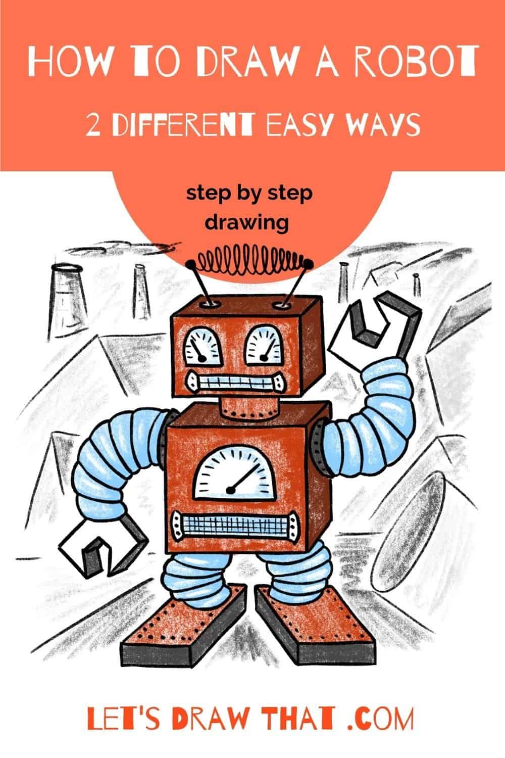
How to Draw a Robot: 2 Different Easy Ways
Learn how to draw a robot. Step by step instructions to draw two very different robots – one old school square humanoid, and one nice round robot on tracks.
The first robot we draw is the classic old school humanoid, made from two square boxes and a “face” built from dials.
Our second robot is made of round shapes for a change: a round cylinder for the body, and bulldozer style tracks instead of legs.
Drawing time: about
These are the favorites we use for drawings on Let’s Draw That that we love and recommend:
Disclaimer: LetsDrawThat.com participates in the Amazon Associates Program. If you purchase a product using a link on our website, we earn a small commission, at no extra cost to you. This is one way how you can support this website.
Love drawing? Never miss a tutorial!
How to draw a robot: a classic square-box humanoid
Our first robot is a classic old school humanoid, made from two square boxes, complete with arms and legs of bendable tube and a “face” made from dials.
To make the drawing a bit more interesting, we have drawn all the boxes with perspective. But feel free to draw just a flat robot, if you want a really simple drawing.
How to draw a robot: sketching the square robot
Step 1: Draw the base head and body squares
Our first robot drawing starts with just two basic simple shapes: one rectangle for the head, and a slightly larger square for the body.
Step 2: Draw two boxes in perspective
The next step is to make our rectangles into boxes. Here we are using the simple method to draw a cube: First, extend the short side lines at 45 degrees from the outer corners. Then complete the box with parallel lines to the original sides. Check out the how to draw a cube tutorial for a more detailed explanation, if needed.
Before we move to the next step, let’s mark out the circles for the neck and arm on the box. Since these are at an angle, they will show as flat ovals on the top and side of the robot’s body.
Step 3: Sketch robot’s neck, arms and legs
It is time to give our robot some arms and legs. We will draw them as simple bent macaroni tubes.
The arms start on the sides – that is what the oval marking was for. One arm is bent up, the other down. They both finish with a small curve, or half oval.
Next add the same macaroni legs.
Step 4: Sketch the hands and feet
Let’s finish the arms and legs with some hands and feet.
Now there are many different kinds of hands you can give your robot, which will depend on what your robot is good for. Our robot has spanner-like hands. The outer shapes of the hand are just open “V” lines. The inner shape is the spanner hex opening or kind of squared-off “U” shape.
For the feet, our robot will have two more simple rectangular boxes. As these are again drawn in perspective, the front and back are horizontal lines, but the sides are at an angle.
Step 5: Add perspective to the hands and feet
Since our entire robot drawing is in perspective, we need to add some thickness to the hands and feet as well.
Again, using the simple method from our cube tutorial, we extend the short lines up at 45 degrees to the right from the outer corners on the hands. Then we finish the shape with a parallel outline of the hand.
Notice how we have touched up the end of the arms so that they smoothly end on the new hand outlines.
For the feet, we have already drawn the lines at an angle. So to complete the box shape, extend short vertical lines from the outer corners and then again finish off with the parallel outlines.
Step 6: Sketch the robot’s face
Since we are drawing our robot very human-looking, let’s give him a face. We will draw two eyes as half-circle gauges. Draw a flat bottomed half circle. Then add the inner needle, and finish the gauge off with some scale lines.
We will draw the robot’s mouth like a square grille, which looks pretty much like teeth.
And while we are at it, let’s draw another gauge on the robot’s chest, just to make it more interesting.
Step 7: Add final details
While now you know how to draw a robot, the plain robot drawing can always be improved with a few extra details. So let’s add them:
Start with another grille at the robot’s “waist” This one is a rectangle again, but this time the mesh is thicker with more cross-hatched lines.
Next, add stripes to the hands and feet. Since these are tubes, the lines have to be curved, rather than just straight lines.
Finally, why not give our robot some antennas, so he can be remote controlled. These are just two lines at an angle, with a spiral antenna in between.
How to draw a robot: square robot outline
Step 1: Outline the robot’s arms and hands
Let’s start outlining and improving our robot sketch, starting with the arms.
There are two subtle changes here: notice the first ring at the shoulder is extended out a bit, to form a kind of socket for the hose that makes up the rest of the arm. And when outlining the arm, we have curved the arm segments into some “Michelin man” arms.
The hands then are a straight simple outline of the sketch.
Step 2: Draw the robot’s head and body
An easy step – simply outline what’s on your sketch. Start with the antenna. Then outline the head box. Then draw the neck.
Next, you can finish by outlining the body, leaving out the lines covered by the neck and arm.
Step 3: Outline the legs and feet
It’s time to draw our robot’s legs and feet. We are using the same trick as with the arms – drawing the legs out as individual puffed-up segments.
Then simply outline the feet.
Step 4: Outline the dials
Here we are outlining the gauges on our robot’s eyes and chest and the two grilles.
And that is pretty much it, now you know how to draw a robot.
Step 5: Add some extra details
OK, this is definitely an optional step, but we can never resist adding yet a few more details. So here they are:
Similar to our train drawing or rocket drawing, you can add some riveted panels to your robot: just draw a line of dots around any of the robot’s sides. Here we have riveted feet, neck, and shoulders.
We have also added tiny riveted sides to both grilles – something that holds them in place and makes them more interesting.
What to draw next:
How to Draw a Train: Step by Step From Simple Shapes
How to draw a robot: finished square robot drawing
How to draw a robot: finished square robot outline drawing
Here is the completed robot drawing, after the usual clean-up of the sketch lines.
How to draw a robot: finished square robot drawing coloured-in
And since we like to complete our drawings in colour, here is one option for colouring your robot.
We thought this boxy robot is looking like a very old and run-down model. So the poor thing ended up all in a rusty brown colour. Only the segmented tubes for legs and arms must be stainless steel – hence they are shiny metal, err, blue colour. Some dark grey for the shading completes the simple colour scheme.
That is it – now you know how to draw a robot. Well, one possible type. How about drawing a very different robot next?
How to draw a robot: round robot
Robots come in all different shapes and sizes, so our second robot is made from round shapes for a change: a round cylinder for the body and rounded off bulldozer-style tracks instead of legs.
How to draw a robot: sketch a round robot step by step
Step 1: Sketch the robot’s base body shapes
Let’s start drawing our round robot with a simple oval – that is the one in the middle, about twice as wide as it is tall. That is the base of the robot’s cylindrical body. To draw the body, just extend the two lines up from the far edge of the oval and close the dome with a half-circle.
Next, we start drawing the rectangle in perspective – that will be the top part of the robot’s wheelbase. Following the familiar easy perspective from how to draw a cube, extend the two lines at an angle from where the robot’s body sides meet the base oval. Notice that the right line goes full length, while the one on the left is half-hidden behind the body. Then complete the platform with two horizontal lines to close the parallelogram (that is a fancy word for the squashed rectangle).
Step 2: Sketch the track shoes
Next, we are building the robot’s track undercarriage.
Duplicate the straight lines at the front, back, and side first. Then, close the shape with half circles to form the track shoes.
Step 3: Add some “face” dials
Even our second robot will have a human-looking “face”. This time, we draw two “thermometers” for the eyes. We draw them with a shape matching our robot’s body: two long rectangles, flat at the bottom, and rounded at the top. Then, repeat a skinny version of the shape for the inner thermometer/eye pupil. Add a scale in the middle – just a simple line with some cross marks.
Then, draw a nice, smiling “mouth”. Again, the same shape as the body, but upside down. Finish it with some cross-hatching – robots do not have mouths, so this is a vent grille (which happens to look like a mouth).
Finally, mark a little oval opening at the side of the body for the “shoulder” where the arm will attach.
How to Draw a Robot
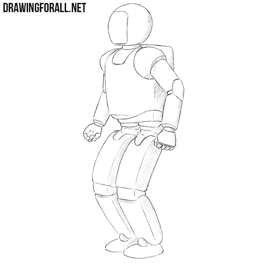
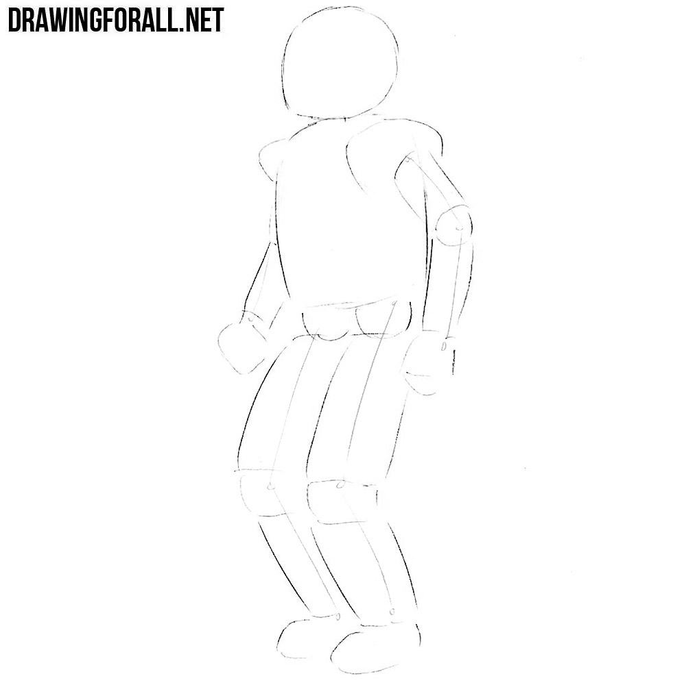
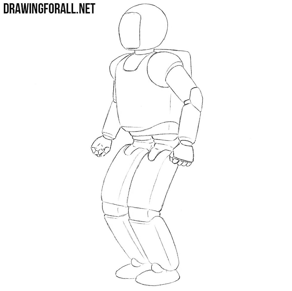
In one of our previous drawing lessons, we showed you how to draw a robot for kids. That lesson was very simple, and many of our readers asked us to make a lesson about a more complex and realistic robot. And so we created a lesson on how to draw a robot.
Step 1
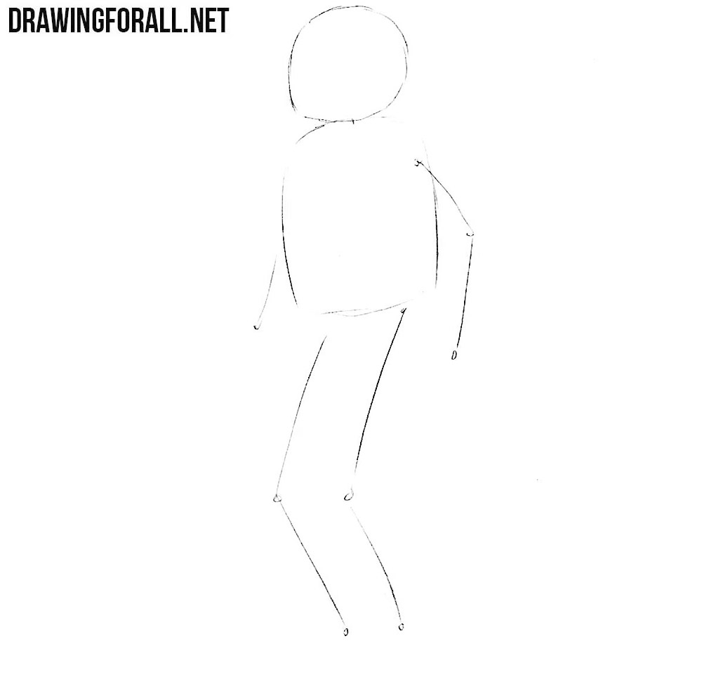
First of all, sketch out the head and torso of the robot in the form of a circle and an oval. Next, we sketch the arms and legs using simple lines. Note that the “skeleton” of the robot is quite different from the skeleton of an ordinary human.
Step 2
Now let’s add the volume to the limbs of our robot as shown in our example. Be sure to outline the connections in the form of circles.
Step 3
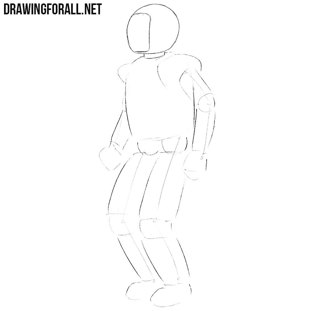
Now using the clear and dark lines carefully draw out the contours of the round head of the robot. At the front of the head draw a contour of the glass.
Step 4
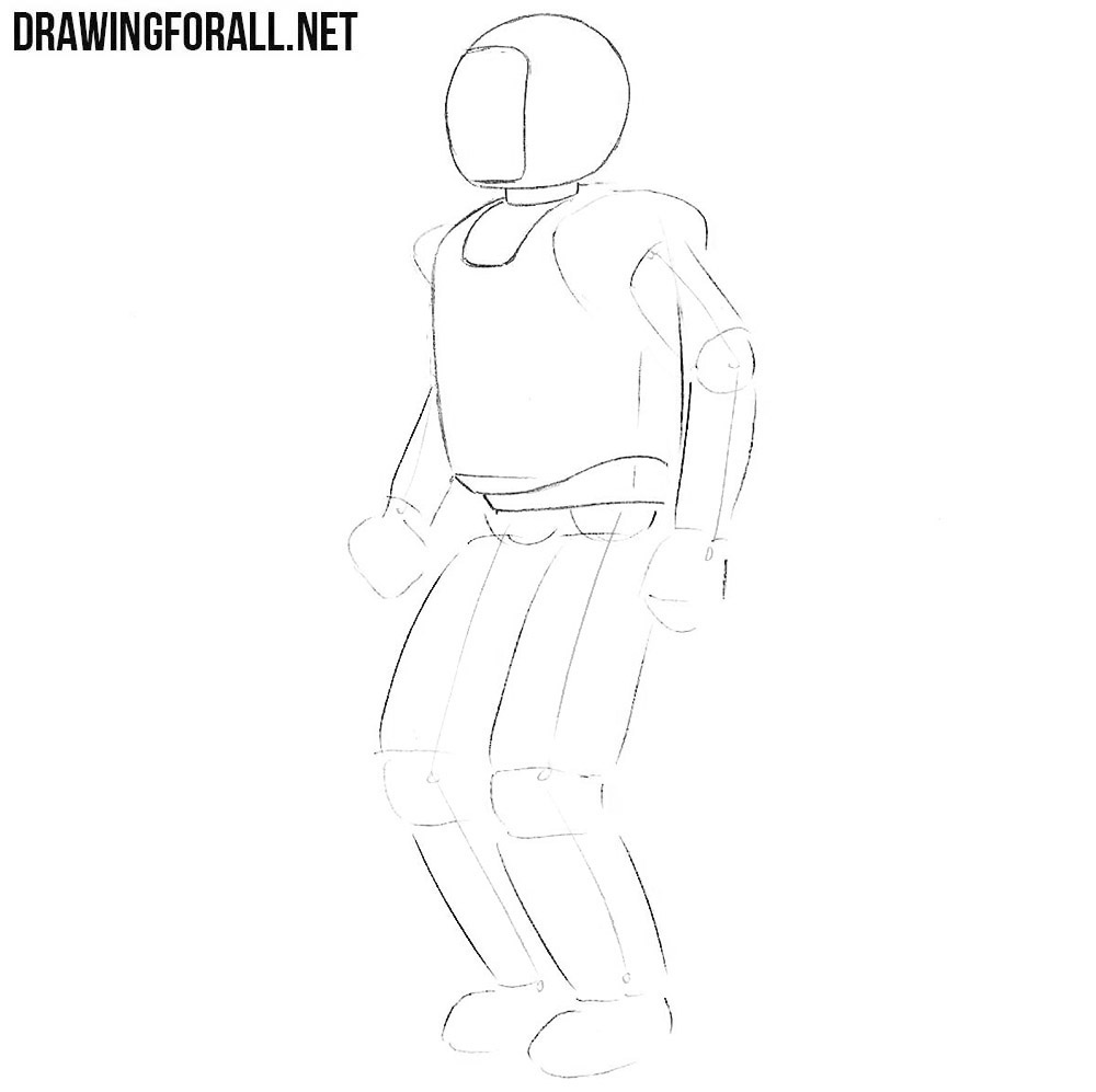
Now move to the torso, drawing it with clear and dark lines. Try to repeat the outlines of the robot’s torso as shown in our example.
Step 5
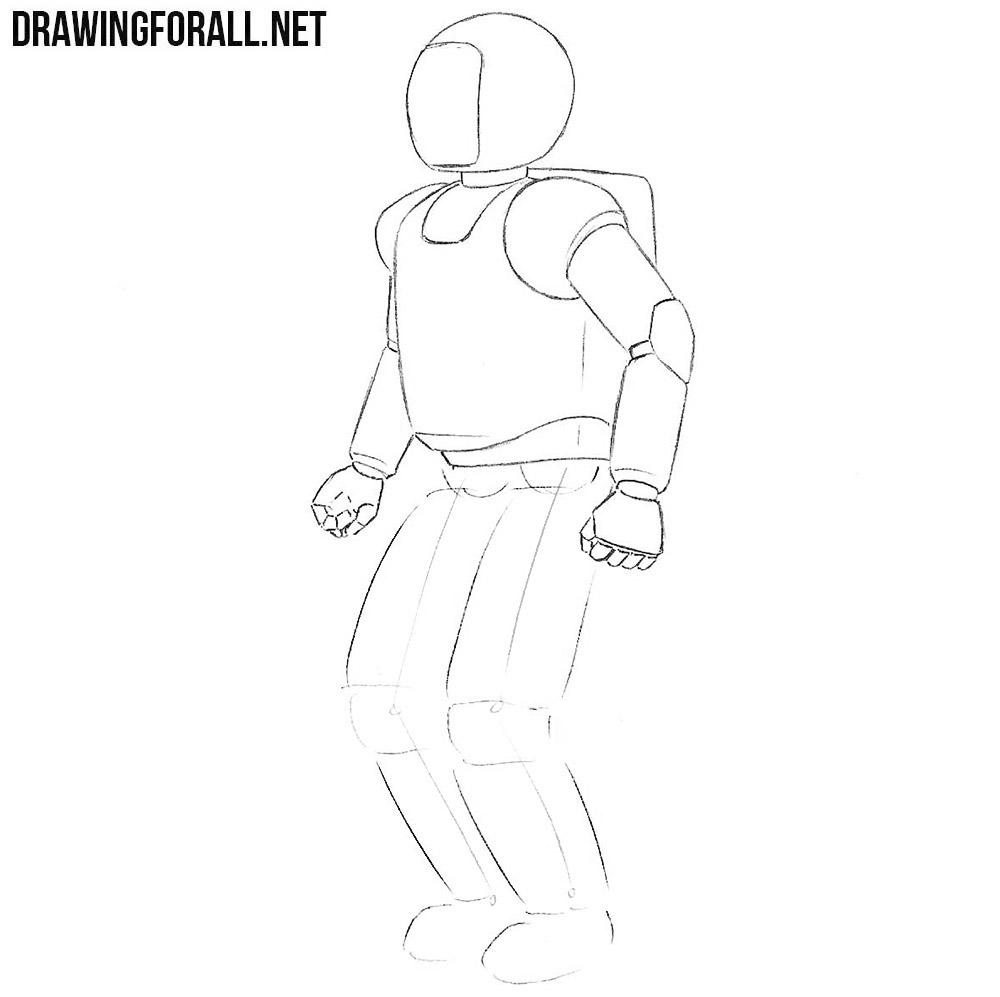
Draw the outline of the round shoulders, then go to the arms and draw out them in the form of cylinders. Draw out the hands and the elbow joints.
Step 6
Now we need to draw the robot’s legs. Note that they are slightly larger and angular than the arms. Repeat all connections and parts as in our example.
Step 7
If you understand that all lines are made correctly, and the result you like, then proceed to the process of drawing shadows. Draw shadows using dense and uniform shading, as in the example below.
In this lesson we showed you how to draw a robot using the example of a very famous Japanese robot. But with the help of our tips, which were shown in this lesson, you will be able to draw any robot. Note that this robot very slightly reminds a man. But there are other robots that exactly match the appearance of a human. For drawing such robots use the tips from our drawing lessons about human. Also we are waiting for your wishes and criticism in the comments to our article or in our social networks.
How to Draw Robots Using Shapes and Forms
Easy Robot Drawing Using Shapes and Forms
It’s really easy to learn how to draw robots, especially if you’re using shapes and forms as your guidelines. There are so many different ways to draw robots. Use robot reference photos for ideas. And then change the way you draw them to make them your own.
The more you draw something the better you will get at it, and the more creative your ideas will be. So it’s a good idea to do several drawings and make some changes with each drawing. And when drawing robots, there’s no shortage of changes you can make.
From the head, the body, the arms, the legs, and whatever else you can think of. Today we’re going to look at some different ways to draw robots. Both with shapes and forms, so we can draw 2D and 3D robots.
Let’s gather up some supplies and get started with some robot drawings.
* Some of the links in this post may be affiliate links. This means I receive small commissions for purchases made through these links at no extra cost to you.
Art Supplies
Shape vs Form
What is the difference between shape and form? The only difference between shape and form is that a shape is two dimensional, and a form is three dimensional.
This is accomplished by adding the third element, depth, to the two dimensional shapes. Shape and form are both elements of art, and therefore are something you should know and understanding if you’re interested in creating art.
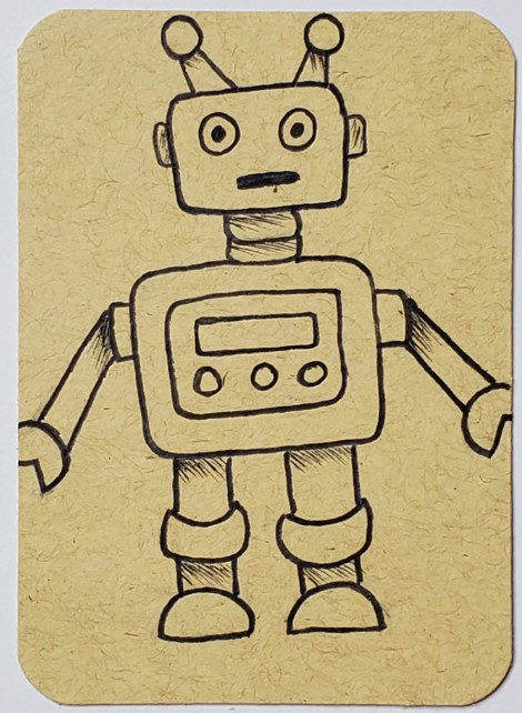
How to Draw Robots Using Shapes
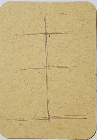
The first thing to do when using shapes to draw a robot is to lay out some rough guidelines. Draw a vertical line going down the center of where your robot will be. Then put in some horizontal lines for the placement of the head, body, and feet. This is to give you a rough idea of the placement of your robot.
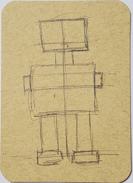
Next, use shapes to draw each part of your robot. You’re not limited to using squares for the head and body. Draw your robot using whatever shapes you think will look good.
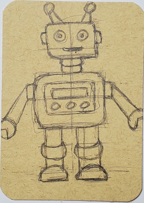
Continue working on drawing out your rough sketch. Add in any details you want to include on your robot.
After your rough sketch is finished, go over your outline with a thin black marker. You can add in some shading with the black if you think that would look good. And then use an eraser to remove your pencil lines.
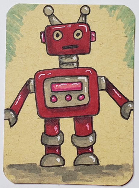
Complete your robot drawing by adding in some color. I’m using markers for this example, but you can use whatever medium you prefer. When adding color try to use more than one color for each section of your drawing. You can use a light and dark value of a color, like the pinks in his lights.
Or, you can add in some gray over a color to show some darker areas. White can be used to add in some highlights.
How to Draw Robots Using Forms
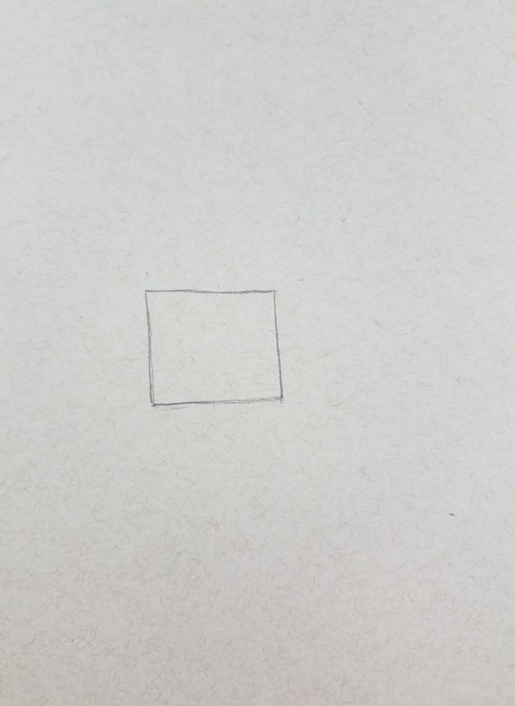
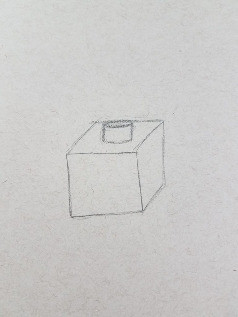
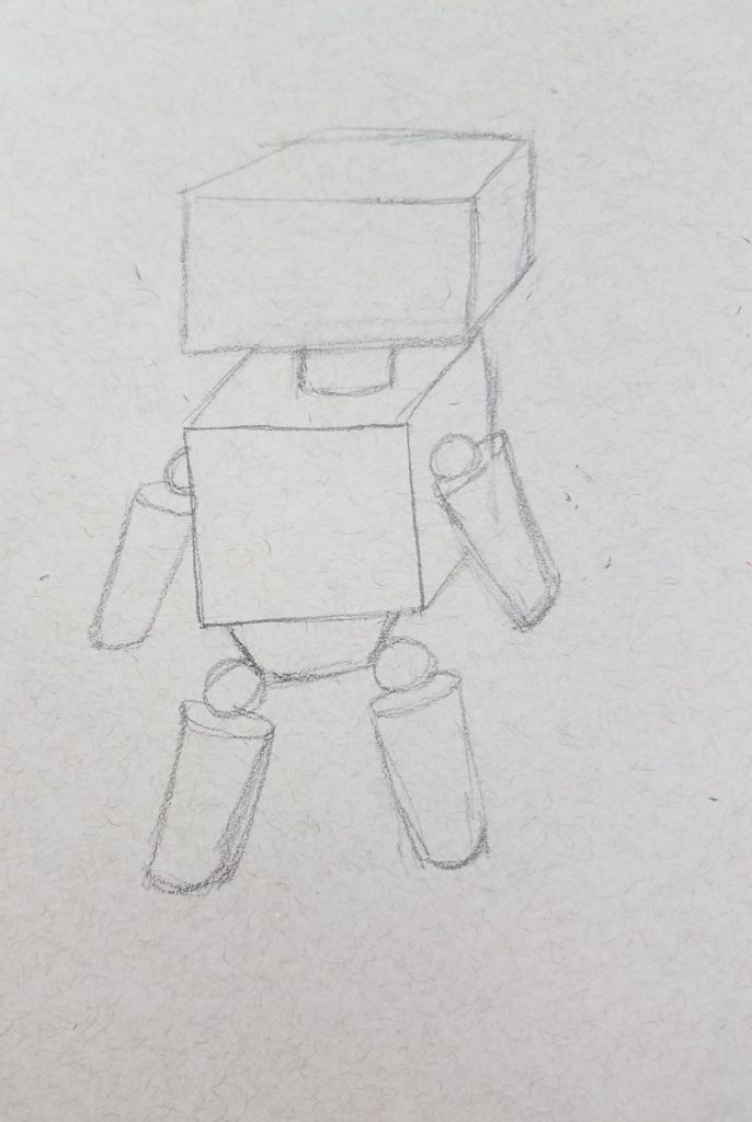
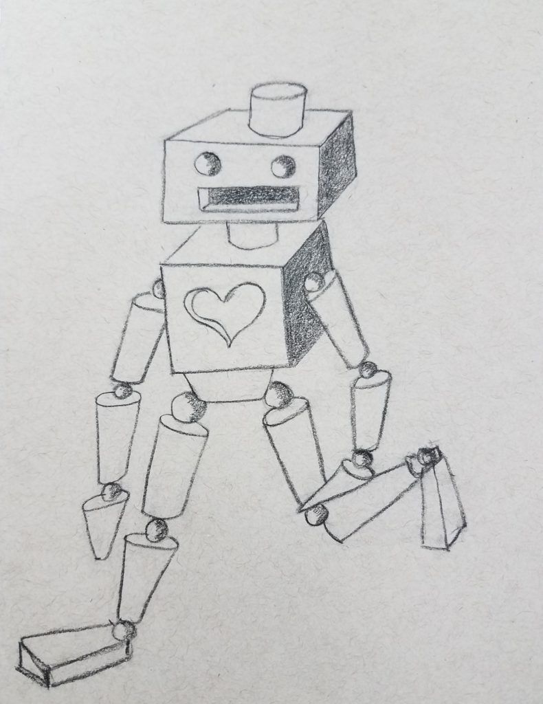
To draw a 3D robot, begin by making a square somewhere near the center of the paper. In the next step, we’ll be turning it into a cube to represent the robot’s body.
Be sure to draw big enough to fill the paper when your robot drawing is finished. We don’t want tiny little robots on our paper when the drawings are done.
Drawing Cubes
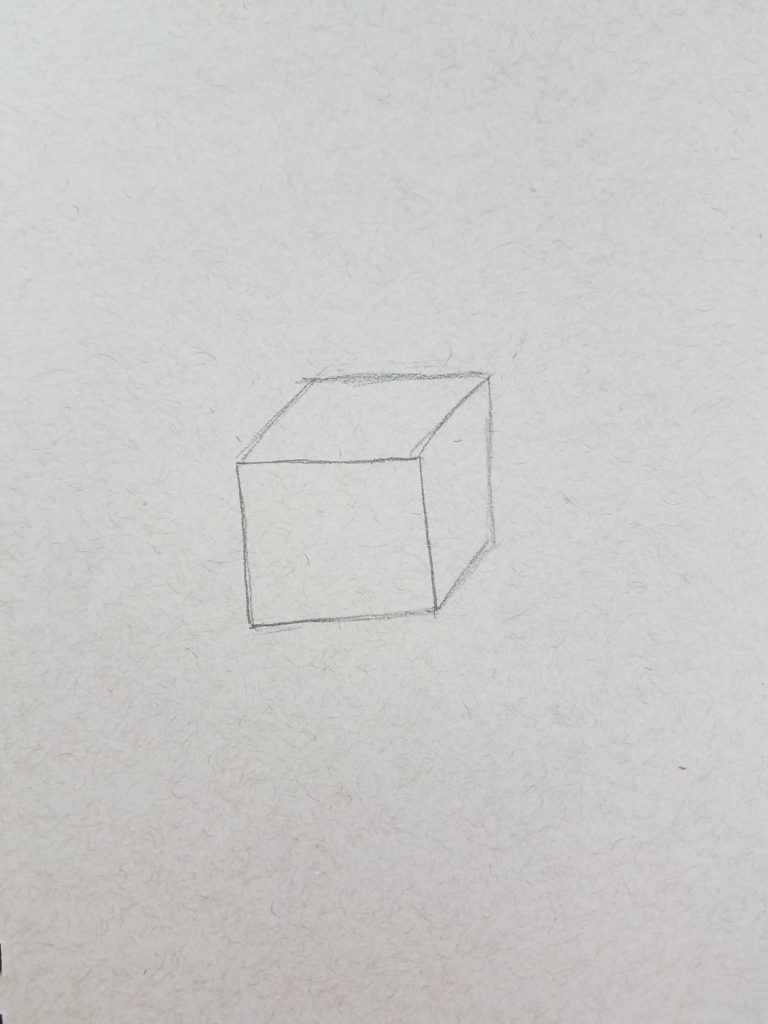
The next step is to turn the square into a cube.
Remember that when drawing a cube, you can see either the top or the bottom, but never both. And you can see the left or the right, but not both.
We have an entire lesson on How to Draw a Cube, which also includes a free handout that might be useful to use as a reference or cheat sheet.
The next step is to add a short cylinder to the top of the cube for the neck. Be sure to place the neck in the center of the cube. If the cylinder is drawn taller, the head will sit up higher from the body.
How tall the cylinder should be drawn is a decision you will need to make, and will slightly change the look of your robots.
In the next step, the top of the cylinder will get covered up. However, the purpose of this lesson is to reinforce the concept of using form in art. And to practice drawing those forms.
Therefore, it’s best to build your robot drawings using the entire form.
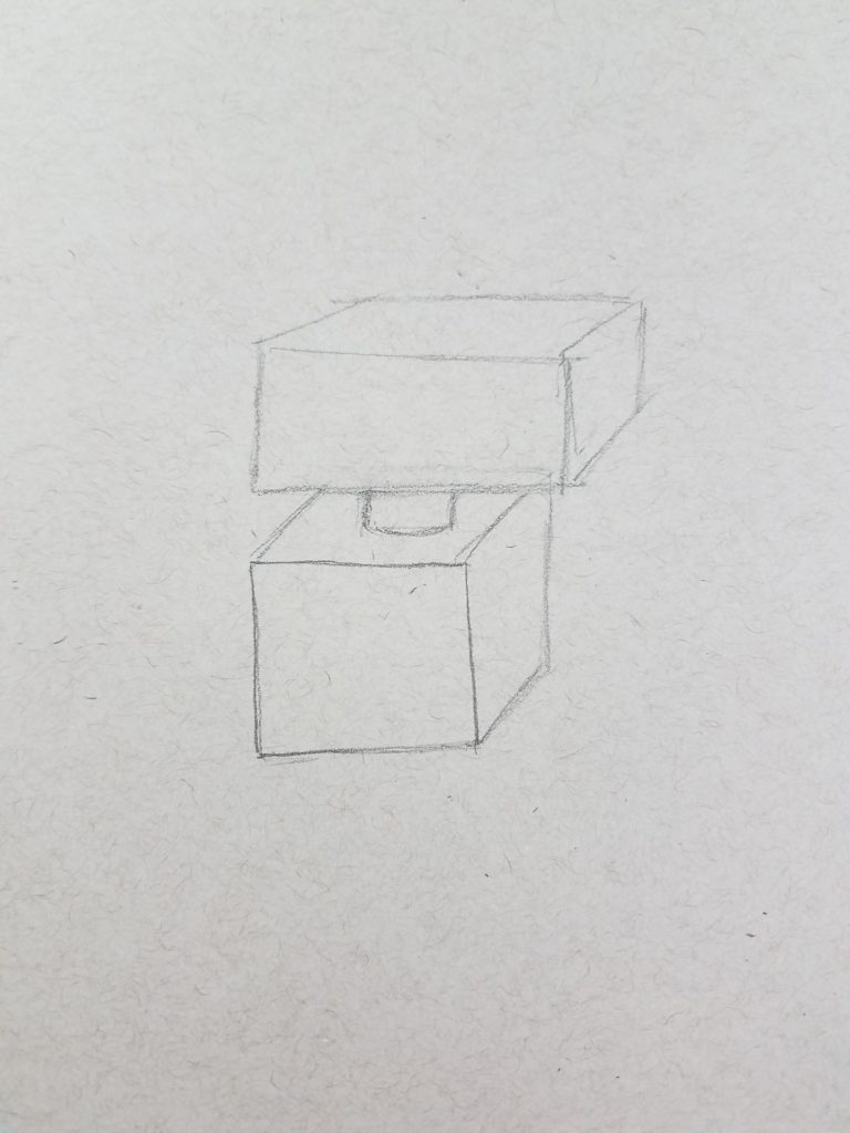
For the head, draw another cube. The shape of this cube, or any of the parts for that matter, will help determine the overall look and personality of your robot.
Don’t be afraid to add own personal touch to your form robot. They don’t need to draw a perfectly square cube. You can draw them longer or taller, just make sure your lines are angled correctly.
Drawing Spheres
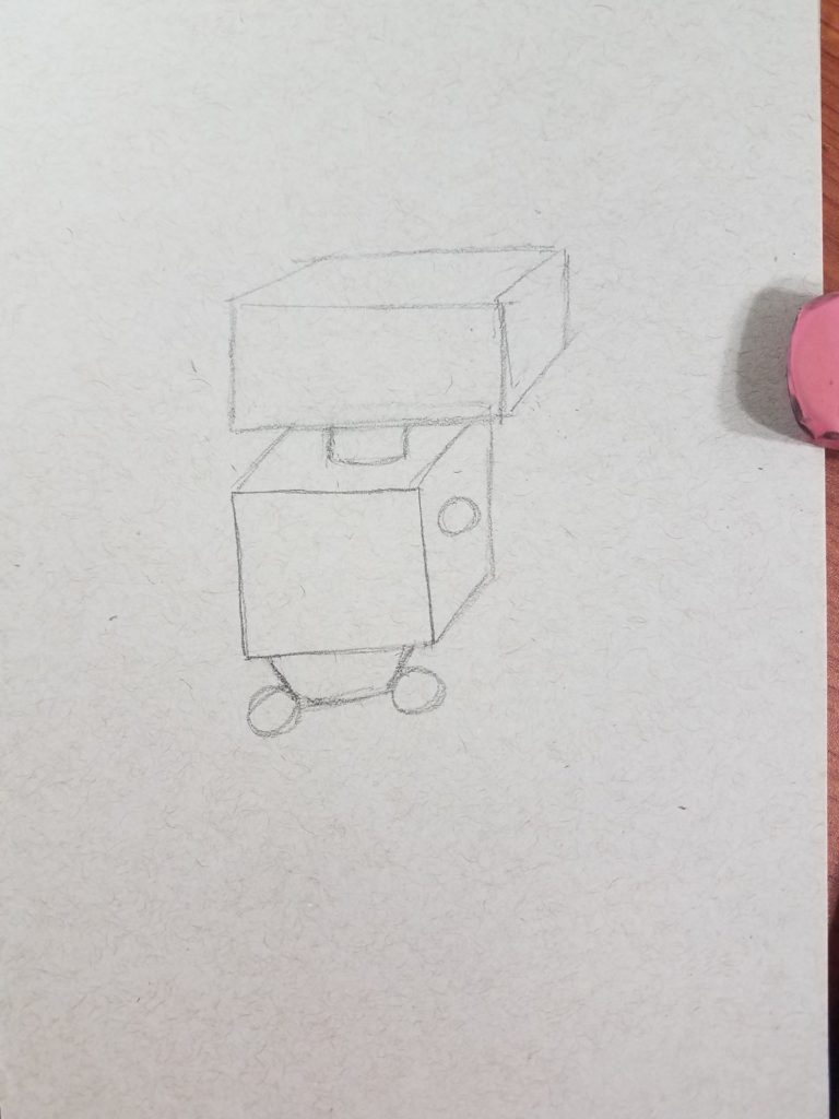
The next step is to add in the joints so the arms and legs can be drawn in. Spheres are used for the joints, to allow the arms and legs to have movement.
An extra piece will need to be drawn below the body to give you a place to connect the legs. This can be drawn however you choose, as long as it’s drawn three dimensional if the shape allows for it.
After all, we are drawing robots using forms and need to use them as often as possible.
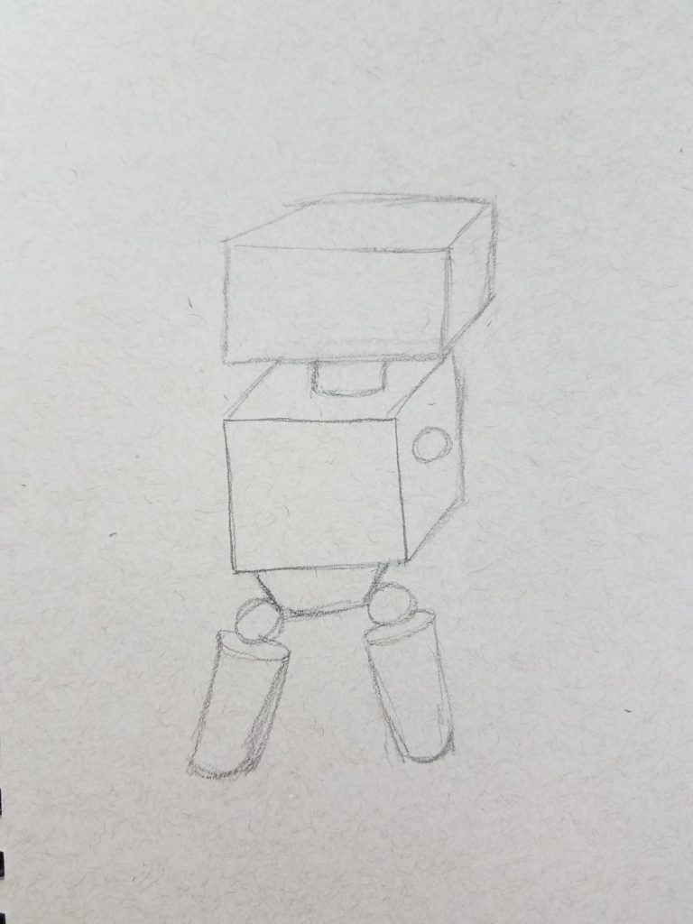
Robot Legs Using Cylinders
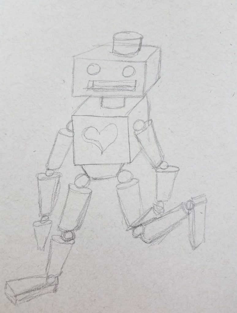
Next, use cylinders to draw the robot’s legs. The placement of the legs and arms will determine the pose the robots will have. You should take this into consideration when drawing your robot.
Whenever possible try to use a reference for poses. Having a visual will often spark some new ideas or give you some courage to be more creative.
We have an entire lesson on drawing cylinders, you can read more about it at, How to Draw a Cylinder.
Cylinders are also used to draw the robot’s arms. Again, different poses can be used to add a little character to the robot drawings.
Form Robot Extra Details
Finish drawing your robot using different forms where needed. Cones can be drawn for the hands, or another shape could be used as well.
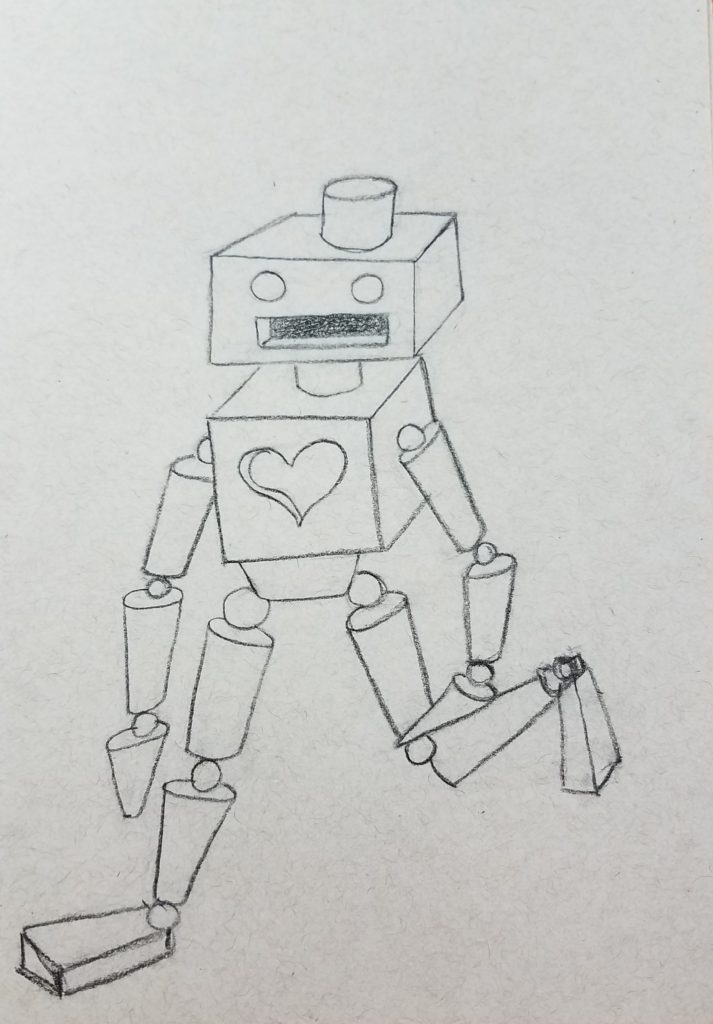
To complete your drawing, add a face and any extra details. A heart was added to this robot drawing, and a cylinder on top of the head for a light.
For more advanced students, you can challenge them to add some cut-out areas to theirs as well.
Shading Forms
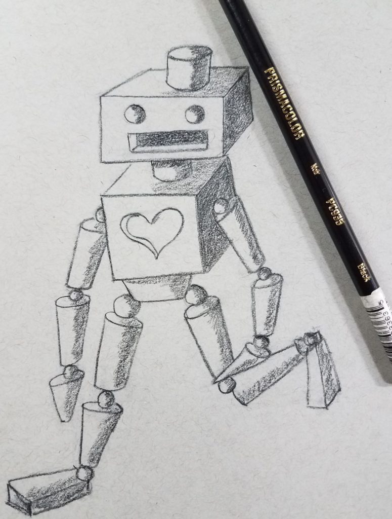
Before adding some shading to the form robots, trace over the pencil lines using a black colored pencil.
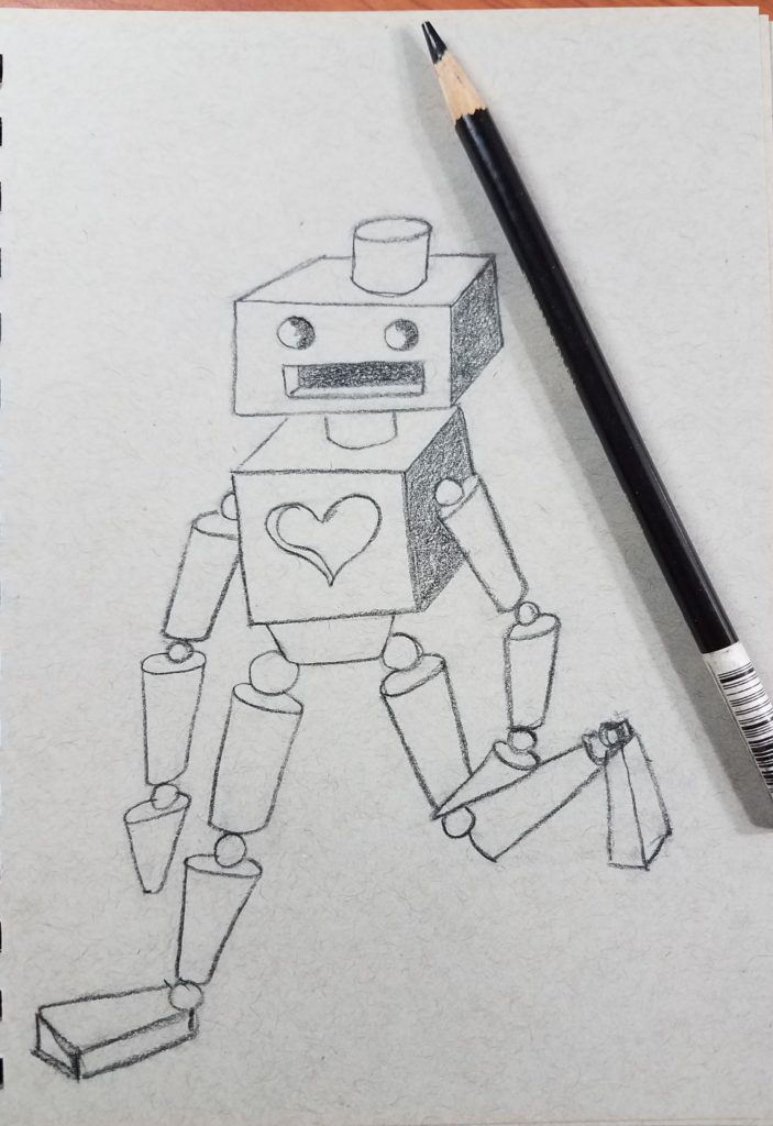
When shading your robot, start with the easy areas first. You can add a light source to use as a reference for the shadows by drawing a sun in the direction you want your light to be coming from. The inside of the mouth and the sides of the cubes were shaded first, since those areas are the most obvious.
Next, I moved on to shading all of the spheres. And then shading everything in groups by the type of form that it was. This helps keep things consistent with the shading and not getting mixed up along the way.
It is important to keep your colored pencils sharp. The best way to do this is by using an electric pencil sharpener. They seem to keep the pencils much sharper, without breaking them as easily. I always buy the ones that have the automatic stop function.
Continue working your way through your robot by shading all the cylinders next.
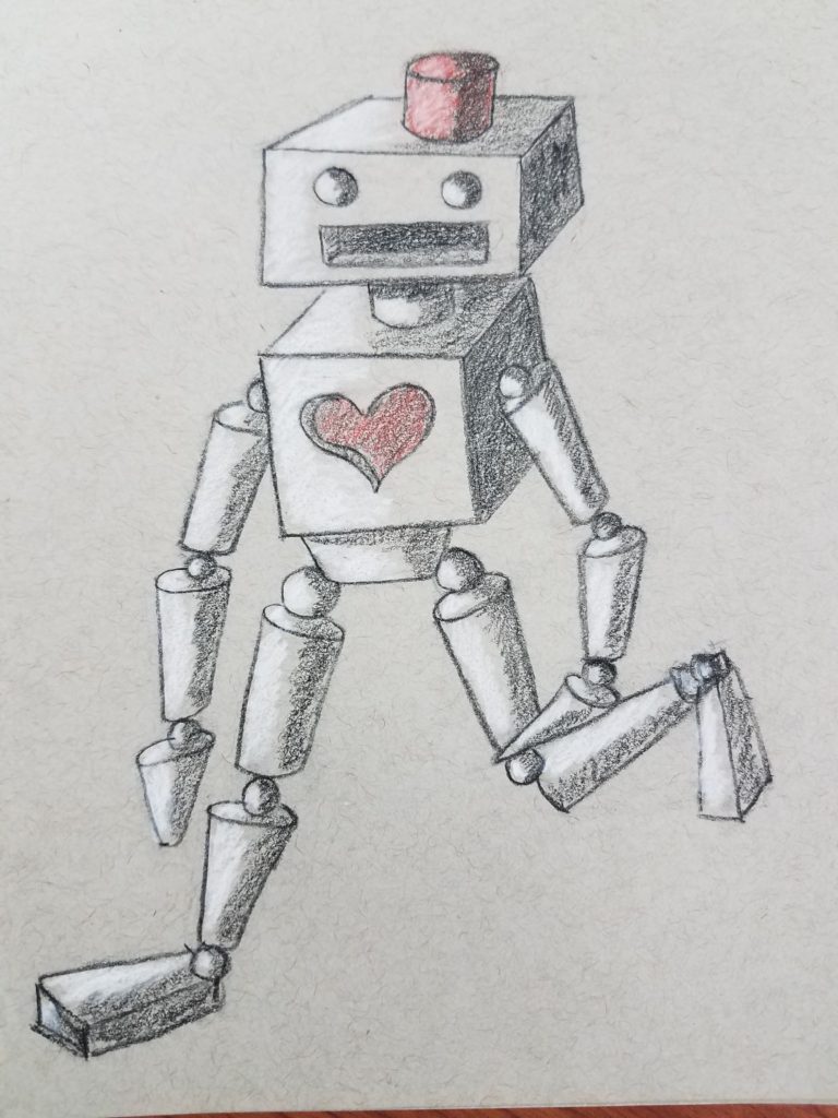
Adding Highlights
The final step in drawing your robot is to add in the highlights using white. In my opinion, this is the best part of the drawing. I love how the white brings it all together on the gray toned paper.
You don’t have to get too technical with your shading and highlighting. The goal is to get a good range of value and tones using only the black and white with the gray paper.
How to Draw Robots Using Shapes and Forms
Learning to draw is a skill that is developed over time with consistent practice. It’s a skill that anyone can learn. When learning how to draw robots, or anything else, it’s important to be relaxed and have fun. You should enjoy your creative time and not feel stressed about how your artwork is going to turn out.
The more you practice the better your skills will get and the more creative you’ll become. Try to focus on the process and not the outcome. Fell pride in everything you make. Try doing a robot drawing challenge and see how many cool robots you can come up with.
Addition Posts for Drawing Robots with Forms
Roshanda is an art education blogger who is on a mission to coach and encourage as many aspiring artists as possible through the use of her blog. Learn more about her on the About Me page and connect with her on Facebook, Twitter, and Instagram.
How to Draw Robots
Robot%2Btoy.jpg)
I love robots. Robots have figured prominently in science fiction for a long time, and were a vivid part of my childhood.
I had robot toys and read robot comics.
Films like The Day the Earth Stood Still, West World, Metropolis and Forbidden Planet all left their mark on me.
When I came up with the idea for Little Robots back in the late ‘90s, it was partly because robots had never, to my knowledge, been featured as the heroes of children’s picture books, let alone a TV series. I felt as though I had a blank canvas to play with.
The robots I finally decided on were a mixed bunch – short and tall, round and skinny, loud and shy, fast and slow.
If you take the simple approach, they can be easy to draw because you need only work with the most basic of shapes. Bodies can be boxes. Arms and legs don’t have to be complicated things with joints and muscles, they can be metal tubes, like those of Bender in Futurama. Robots can have two legs or three or more; they can have wheels or tracks or jets to fly with. Their hands can be simple pincers or suckers like those of the Daleks. Their faces need consist of nothing more than circles, triangles and rectangles. Stick a few rivets on the body and you’re done.
But if you want to try something more complicated, I’ll point out a few problems I remember encountering when I was drawing my characters in Little Robots. They might serve as handy do’s and don’ts. I wanted them to look properly 3-dimensional and work from all angles, partly because I had a secret hope that one day they’d make it to the TV screen as animated characters. I also wanted a grungy, mechanical look to my robots, as if they’d ‘grown’ out of a junkyard, or been re-discovered in a Victorian inventor’s old laboratory, rather than having a shiny, hi-tech appearance, so these are some of the things I thought about…
• Faces. If you’re dealing with small children you’ll have to invest your robot with some personality. Immobile and expressionless robot faces like those of the Cybermen (for me, always far scarier than the Daleks!), are really creepy. Logically, robot faces won’t naturally have any mobility, as they’ll be made of metal, so you’ll have to cheat like crazy to enable them to show emotion. I tried to think of a robot face as being made up of cogs, hinges and widgets that moved about in a mechanical way. It was easier to imagine them being animated that way. Alternatively, I’ve created robot faces made from a TV screen before now, so that a variety of expressions could be shown in a plausible way.
• Think of other mechanical devices that might be used on your robot to emphasis its metallic nature – TV dishes instead of ears; telescopes for eyes; springs and shock absorbers for the arms and legs; rivets and screws; pressure gauges and flashing lights.
• Creating your robot’s world. A good exercise is to go into a typical garden shed, DIY toolbox or an ordinary kitchen for that matter, look at all the gadgets you can see and, (with the appropriate permission!) try assembling some of the objects into a mechanical creature.
Similarly, if you want to create an unusual, mechanistic environment, try taking old pots, pans, cans, perfume bottles, widgets and doo-hickys from your cupboards, and assemble them into something resembling a townscape. Turn some of the bits and bobs upside down or sideways, and you’ll find unusual shapes reveal themselves. Draw the shapes and embellish them until they become your own robo-town.
Reclamation yards and antiques fairs are other wonderful places to come across strange and unconsidered objects. Victorian mangles, old hoovers, spare parts from 1950’s cars, sci-fi memorabilia – there’s a world of inspiration waiting there for you!
• I wanted to give my robots a variety of finishes to make each stand out from the other so, for example, some had a shiny appearance, some had a rusty look. As an experiment, try drawing a rusty piece of metal, then a reflective piece of metal like a car bonnet. It’s a tough visual problem but you’ll learn a lot about observation.
Finally, school visits. When I go into schools I’ll often do How-To-Draw sessions with the children, but I’ll also take various printed sheets, such as the two shown here, that can be photocopied for use in class after I’ve given my talks.
It’s an easy way for teachers to do follow-up work with the children. If they’re too young to do creative writing or drawing, many of them like to take these sheets and colour them in, cut them out and stick the bits together. I encourage them to use the sheets as a starting point, and to go on to make their own robots, which often results in some spectacular results! Why not try something similar?
DIY Arduino Drawing Robot
Introduction: DIY Arduino Drawing Robot
In our lives, art is everywhere, even cold tools like robots can bring us a lot of fun about art. When I saw Euphy’s video, I saw a new possibility of drawing robots, it was great to see them turn something virtual into a real entity, it can automatically hold a pen and draw on the surface of paper or any object, and the platform for drawing is not only limited to the horizontal plane, you can also try it on the wall.
The wire pulling wall painting machine is a very early project, but there has been no better solution for machine reasons. Recently, we have elaborated a rather excellent solution to the problem of stepper motor mount and pen holder. Stepper motor using 28byj, small size, easy wiring, simple procedures, no driver, welding, power supply, and other issues, can be used by Arduino direct power supply. Motor and motherboard integrated with a base, both sides have a winding frame that can be pasted on any wall, the upper corner of the drawing board.
Let’s get started and see how to archive such an amazing project!
Step 1: Bill of Materials
The project is composed of the following components:
Motor bracket x 1
28BYJ-48 Stepper motor driver board x 2
SG90 Servo motor x 2
Micro SD card adapter x 1
Arduino sensor shield x 1
Pen up steering gear x 1
Step 2: Base Bracket Assembly
The first step is simple, first, we find 12 large head screws and 12 brass posts, screw the large head screws in from the back and fix all the brass posts
then we installed the motor driver board in order for the Arduino to drive the stepper motor. The motor driver board is required because the Arduino’s output pins do not provide enough power directly to the stepper motor, which requires a 5V power supply to operate.
Lastly, install the two Arduino UNOs on the brass posts and finally fix the SD/TF card reader on the top with the smallest screws.
Step 3: Stepper Motor Bracket Assembly
There is a lot to do in this step, but it is not difficult, it just requires more patience. There are 3 steps to motor installation, which I would like to express as follows.
1. Mounting the motor
-1. Prepare a motor stand by breaking it off and then reassemble the board according to the second diagram.
-2. Downwards, fix the riser handpiece with screws and then install the motor.
2. Making the spool
-1. Tie the cable loop to the end of the cable, pull the cable into the gap on the back of the power cable and then check the cable around the spool.
-2. At the other end of the pull cable, tie a thick cord that can be used for the pen in the next step. The cover plate then covers the hole in the bracket plate and is fitted into the hole in the bracket.
-3. Use the screw holes to mount the motor bracket on the end of the drawing board or wall so that it is at the same level.
When winding the wire, remember to wind the left bobbin clockwise and the right bobbin counterclockwise.
3. Pen holder assembly
-1. First, we need to break the barrel-shaped pen that needs to be installed, insert the exit cargo screw at the large end through the mouth and tighten it.
-2. After this, we install the drone. As shown in the picture, the centre of gravity is at the very centre after installation for smoother running.
-3. Next, use the large end to secure the left and right side panels and the shaft cutout. Remember that the screws that rotate the shaft should not be tightened.
-4. Once you have determined the position of the pen, tie it off with a string. When adjusting the position of the pen, it is perfect for the ultimate drawing quality that allows the pen tip to touch. Hold the pen holder as well as possible.
So far, the motor bracket has been completed.
Step 4: Connection
2.The pen lifting steering gear can be connected to 13. The steering gear cable is brown GND, red VCC, and yellow is the signal. If you use an SD card reader, you can connect to the A0 port.
Notes:
-2.SD or TF card reader module does not support SDXC above standard card, please choose a relatively old small capacity card, will have better performance compatibility. Generally, cards of 16g and below are formatted in FAT32 format, not NTFS or exFAT format, and can be used for Use. Some TF to SD cardholders may also have incompatibility problems. If the only TF card is available, the TF reader module is recommended.
Step 5: Programing
We will provide you with the corresponding code, but there is still a part of the code that needs to be modified according to your actual size, the part of the code that needs to be modified is as follows.
1. First run 2Steper.ino, the function of this program is to make the stepper motor work and draw a pendulum graph, it is relatively simple, just adjust the number of revolutions to change the pattern. The position may be much worse, and when running the program directly, the pendulum arm may turn to a completely irrelevant position, which is troublesome.
2. The main program is WallDrawDemo.ino, which will draw a few patterns for testing. Do not install the pen yet (the cord holder can be hung on the pen stand), run the program, let the pen stand run empty for a while, and see if the running range, whether within the paper range. If it is beyond, the parameters still need to be adjusted, the specific efficacy of several parameters see the program notes The effects of several parameters are described in the program notes.
3.The next step will be uploading our code to the Arduino board, the code can be found at the bottom of this instructable, make sure that you choose Arduino Uno regarding the device you use (Arduino Uno) in the ArduinoIDE.
If you are not familiar with Arduino, follow the following steps:
-1. Connect your Arduino board by USB to your computer
-2. Open Arduino IDE (if you don’t have it, make sure to download it from their official website)
-3. Open the project we gave at the bottom of the Instructable page
-4. On top of the Arduino IDE choose «Tools > Board > Arduino Uno,and select the port number COM corresponding to the board( (please install the Ch340 driver for unrecognized devices)
-5. Click the V sign to verify the code and then right next to it the arrow-right button to push the code!
Attachments
Step 6: Upload the Images You Want
When you have finished debugging the previous steps, you can upload your own desired image for drawing.
How to upload your image?
Not any photo can be drawn, only vector drawings can be drawn. Fortunately, some photos can be converted into vector drawings by software. (You can use Coreldraw, Inkscape, and much other software processing) or take a simple vector drawing to try first.
1. Vector drawings should be converted into gcode files. Gcode is a text file that can be opened and edited with a writing tablet. Before using it, you can browse the values in the gcode, these values are in actual millimeters, if there are thousands of thousands of values that can be catastrophic to make the stepper motor turn for hours before it stops. Specific gcode rules and use of many online, you can learn on your own.
2. Gcode file is saved in the memory card, Arduino reads the file from the card, and the position coordinates are resolved into the action of the stepper motor, pulling the rope to drive the pen to draw. (WallDraw.ino program in the package can perform this step)
-1. The memory card preferably fat32 format, ntfs format may not be able to read the file, especially the 32G capacity of the card or more.
-2. The file name of the Gcode file should be the same as the one defined in the program, usually «1.nc», if it is different, please change it to the same name.
3. Then you need to brush the WallDrawGCode program in Arduino. Connect your computer and Arduino with a USB cable and open CNCjs on your computer.
-1. First, use XLoad to swipe the compiled BIN file into the Arduino
-2. Open the WallDrawGCode.ino.standard.hex file we provided to you in XLoad, select Uno for Device, COM for your port, and 115200 for Baud rate (please install the Ch340 driver for unrecognized devices)
-3. Finally, click the Upload button, the status bar will show Uploading. prompt, close it after success.
4.After uploading the program to Arduino, install the CNCjs application on the computer side, select Grbl, the port number will be displayed automatically after searching, select 115200 for baud rate, open it and establish the connection.
5.After a normal connection, the console will show the following content. And there is an OK prompt.
You can test it by typing a simple GCode after the prompt.
G01 x0y0z0 // Drop pen
G01 Z1 //Lift pen
If the test is OK, you can open the GCode file and start your drawing!
Step 7: Conclusion
In the process of making we also encountered many problems:
1. The first important point is that the fixed pen should only reveal a little bit of the pen frame on it, do not stick out half of the pen, which will lead to not lifting.
2.If your tiller swing arm has been moving in the upward position, can not lift the pen holder. The simple solution is to take off the servo arm and replace it with one that can lift the pen holder and then install it on the servo spindle. Or adjust the parameters of the servo in the program to let the servo change the rotation angle. Do not rotate the servo with electricity, it may damage the servo.
3.In addition, the drawn image is seriously distorted. The solution is to first confirm whether the direction is normal. If you are testing with Walldrawdemo’s program, the nine-pattern is at the top, the peach heart is at the bottom left, and the butterfly curve is at the bottom right. If the direction is wrong, first refer to the previous question and modify the direction. In most cases, the deformation is due to the wrong direction, so the size is wrong. If the direction is correct, the size of the x-axis measurement does not appear too much error, there is no serious deformation.
4.Be careful that if the motor spool is spinning wildly drawing is not normal.
5.Another situation is that, If you are drawing with GCode, it may be that the size in GCode is too large compared to the drawing board size, so the spool will keep spinning, even if the pen holder has hit the motor holder, or the spool is still spinning after it is completely released. Check if there are very large values in the GCode, like G01 X7777 Y6666 or some such code.
6.Last but not least, the drawing board is small, for example, the pitch is only 150mm, but the gcode exceeds the size of the drawing board (for example, an A3 size file is used), the calculated value will overflow and the motor will keep selecting the rotation.
Thank you very much for reading my work and hope you enjoyed my article this time! And if you have any questions, just leave a comment or send me a message.

%2BStrange%2BTales.png)
%2BThe%2BDay%2BThe%2BEarth%2BStood%2BStill.png)
%2BMetropolis.png)
%2BForbidden%2BPlanet.png)
GiantRobots.W%26P.jpg)
LR.TitlePage.W%26P.jpg)
LR.Spread.W%26P.jpg)
%2BStripy.W%26P.jpg)
%2BTiny.W%26P.jpg)
%2BRusty.Shiny.jpg)
%2BSporty.jpg)
%2BRobotCutOutBody.jpg)
%2BRobotsBits%26Bobs.jpg)


