How to make robot
How to make robot
Robotics for Beginners | How to Make a Robot for Kids?
This post is for people especially beginners and kids who are getting started with DIY robots and robotics; nice and easy robotics for beginners post. In this robotics tutorial, we will guide you through the basics of ‘Robotics for Beginners’ and you will learn how to how to Make a Robot for Kids easily.
Getting Started with Robotics for Beginners and Kids
In this post, we will explain – What is a Robot, How to Build a Robot for Beginners, different parts of a Robot, how to make a robot for kids, what are the things to be taken care to get the best robot kit for kids, choosing the best battery for the robot, choosing the best microcontroller for the robot and in the end, you will build your own robot. Let’s get started.
How to Make a Robot for Kids?
Before answering ‘How to Build a Robot for Beginners?’, There is another thing you should know; another question you should answer first – ‘What is a robot?’ A robot is simply an electromechanical device that will sense its environment, process it, takes a decision by itself and reacts to its environment without manual intervention.
Robotics for Beginners Video Guide – How to Make a Robot for Kids?
The path to DIY Robots
Robotics is nothing new to RootSaid, considering how well we are accustomed to using modern tech right from our childhood. Internet technology is nothing new to us, and the pandemic has even forced them to take our own education fully online. DIY Robots should’ve come naturally to our current generation, but it seems our education system is a bit slow on catching up with the latest trends in tech. So we usually find kids in their late teens getting their first real taste at robotics. Considering how widespread the usage of robots is in industries both big and small, their contribution to mass production and precise machining is unparalleled.
This enormous speed and efficiency that machines – especially robotic machines – bring in enhancing our lives have not been limited to industry floors or in high tech military applications. For example, we now see drones people use for recreation, which were once considered very difficult to build. The same goes for many other systems that were previously considered difficult to be made by enthusiasts with short budgets.
Just like any new technology, the DIY trend to tinker around and see what it offers has repeated for DIY Robot as well. This trend got accentuated by many factors: reduction in the prices for sensors, options for quick prototyping, availability of cheap microchips, and above all an ever-spreading supportive network of creators to help fellow tinkerers.
Another major contributor to the falling barrier of entry for DIY robotics enthusiasts is the entry of sensor-embedded garments, virtual reality modules, and similar high-tech devices that were previously unavailable for low prices. This trend is sure to continue in the coming years, with more and more advanced tech made available at approachable prices with the option for customization.
In India, the boom of internet technology in addition to computers and mobile phones paved the way for a wave of white-collar jobs that’s still in high demand. We are now witnessing a new wave of cloud, AI, and robotics tech that’s bringing in new opportunities in the hardware domain, also requiring appropriate programming skills to create turnkey solutions to novel challenges.
It is extremely important that we introduce these essential aptitudes to school-going children as well. Much of what the future of 21st century offers could perhaps only be tackled by adequate DIY knowledge, along with basic coding acumen for software and hardware projects. This judgment is based on research done by PeopleStrong, where it was found that one in four employment cuts globally would be from India. Thus, it is more than just good practice to introduce kids to robotics, it’s high time.
Robotics for Beginners – What are the Parts of a Robot?
As this is a Robotics for Beginners Guide, I will try to make it as simple as possible. To make it more understandable, imagine a robot is like any other organism; like a human being.
We have sense organs. We see things with our eyes. We hear things with our ears, feel things with our skin, taste with our tongue, and smell with our nose. Our neurons transmit the signals from our sensors to our brain where we process them. Our brain process the signal takes a decision and sends the signal to our muscles to move our hands, legs or do whatever we want. Then we have a heart that circulates blood, supplies oxygen, provides energy for the working of your entire system. Then we have a body, where the sensors, muscles, heart, veins, and all other parts are neatly ‘assembled’.
This is the same as in the case of a robot.
1. The Robot Chassis – The Body of the Robot
A robot has a chassis/ robot frame; which is similar to our body. A-frame that will support the whole robot. A system which is having enough space and is capable of handling the weight of all the sensors, power source, and all the cables used in the robot.
Qualities of a Good Robot Chassis for Kids
Here are some of the best robot chassis which are available online to make your own robot.
2. Sensors – The Sense Organs
Basically, sensors are specially designed devices or objects that will detect the properties, events, or changes in the environment, and then provide a corresponding signal. They are one of the crucial instruments which will bridge the physical and electronic world. There are different types of Sensors.
Learn to Make Robots Without Knowing How to Code
If you’re reading this, then robots probably look cool to you. You might be inspired to learn to make a robot yourself because of shows like BattleBots or maybe you just want to create a helper around the house like iRobot’s Roomba. The truth is, there are much easier roads to travel in programming than learning robotics, but there are few as rewarding either.
So where do you begin? If you’re not in a high school or college robotics club, it can seem like robotics is impossible to get into.
If you follow these steps and invest the resources necessary to learn—robotics can be an expensive hobby—you’ll be programming robots to do all kinds of things for you sooner than you think.
Learning to Make a Robot, Starting From Scratch
Scratch was originally developed by MIT as a way to teach kids game programming by using pre-written blockly-style pieces rather than text code.
The block-structure still teaches the fundamental knowledge and skills you will need to know in order to start programming with text and it is the perfect place to start, especially since your first few robots will be programmed using this same visual programming model.
Evo App-Connected Coding Robot
The Evo Coding Robot is a good first robot to work within that its usable right out of the box. It’s small, requires no assembly, and no extra parts; it’s just you, the robot, and your code. There are two ways to program the Evo: online using a similar blockly system that you saw with Scratch, or you could use the color-coded markers to create visual cues for the robot.
While the markers are interesting in that they show you how a robot can use sensors to make decisions, where you really need to spend your time is working with its blockly system, which will serve as your primary programming tool for your next few robots.
UBTECH JIMU Robot Astrobot
The Astrobot isn’t exactly Boston Dynamics, but it’s a good start. This robot kit will serve as an introduction to common robot parts and design features and it’s easy to start building something right away.
It uses the same kind of blockly-style programming that Scratch and the Evo do, so after some time with the Astrobot, you should start getting comfortable with the idea of loops, if-else conditional decision making, nested commands, overall program flow, and how to debug code that isn’t doing what you want it to.
Don’t worry if you’re awful at it, we all were when we started, and these essential programming skills are developed over a lifetime, not overnight.
LEGO Mindstorm EV3
You may not have known it before, but LEGO has one of the coolest robot lineups out there in their Mindstorm product line. Beginning with a central CPU block called an Intelligent Brick, there is an unlimited potential for creative robot building using existing LEGO pieces and add ons for various sensors.
The EV3 programming software is a different form of visual programming blocks that is specific to the EV3 robot but don’t worry. The dirty, little secret to programming is that once you learn to program in one language, other languages become much easier to pick up since the fundamental principles of programming do not change from language to language.
With the EV3, you could stop here and spend a lifetime building cool, sophisticated robots that do all kinds of things. But if what you’re looking to do is build the kinds of machines that you see in BattleBots or similar shows? From here on out, you’re going to start building toward more custom-built machines of the sort we think of when we think about robotics as an industry.
Learn Javascript
From here on, you’ll need to start programming in actual, textual code blocks, rather than blockly, and a great place to start is with JavaScript.
JavaScript is a good language for beginners just starting to work with text code because it doesn’t require the programmer to do the kinds of minute program management that you’ll ultimately need to do yourself when you begin working with C/C++.
Now is the time to begin the time-honored programmer tradition of going out and buying a programming manual for a new language. O’Reilley and Apress make some excellent programming manuals if you want a physical copy or you can find any number of free resources on JavaScript scattered around the Internet and YouTube.
Sphero Bolt
The Sphero Bolt might remind you of the Evo Coding Robot, and you wouldn’t be wrong, they are both very similar from the outside. Inside, however, you will find a more sophisticated programming setup that allows you to implement all that JavaScript you’ve learned.
The Sphero Bolt is the first robot you’ll buy that you can program with text code but it also uses blockly to ease the transition if necessary. Once you’re comfortable programming the Sphero Bolt, you’ll be ready to make the most significant jump yet.
Learn C/C++
C/C++ is one of the oldest languages still in use today, so it has a lot of relics of the era when programming was much more functional and less open-ended than it is today. This means that a lot of the hidden work of JavaScript is now your responsibility, which can make it one of the most difficult languages to learn.
However, C/C++ also has unique advantages over newer languages that tend to manage fundamental operations for you. The most important being that C/C++ is much closer to the machine hardware than other languages, so it is the lingua franca of robotics (and high-performance game development, but that’s another article).
Invest in a solid C/C++ for Programmers manual and start getting used to pointers, static typing, preprocessor instructions, and all the rest, but as you go, you’ll be working with robots that are functionally no different than the stuff Boston Dynamics is putting out.
VEX Robots
Like LEGO Mindstorm, VEX Robot Kits allow you to build sophisticated machines using modular bricks and pieces, so you are limited only by your creativity, the available parts, and the strength of your program. These kits are the major educational tool for robotics clubs the world over, so you will be doing the same robotics programming you see in robotics championships and competitions.
VEX robots can be programmed in 4 different ways using the VEX Coding Studio. It uses a version of blockly called ModKit Blocks to get you started before transitioning to Modkit Text, which introduces text programming to the mix. Next, you’ll have VEX C++, which is an assisted form of C++ that will help you gain your footing before you move fully into professional, industry standard C/C++ programming.
Designing And Building A Robot
Introduction To Robotics And Robot Making
The Terminator. R2-D2. BB-8. Megatron. WALL-E. For years, robots, automatons or otherwise synthetic assistants have been part of our popular culture. While they’ve mostly been restricted to the silver screen, thanks to increasingly affordable and powerful electronics throughout the last couple decades, building a robot has never been easier.
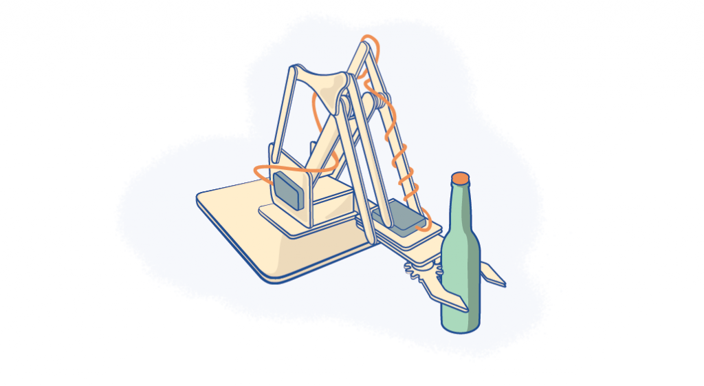
Although robotics is more accessible than ever (such as the MeArm illustrated above that you can build with nothing but a screwdriver and enthusiasm), any robot is a complex system and requires a basic understanding of electricity, mechanical design and programming to create. Never fear! This article will walk you through the elements of robotics, custom robot design considerations, what’s needed to start building a robot PLUS tons of laser-cut design ideas to spark your creativity so you can sell your bots for a profit or cleverly use them to build a brand.
While making robots can be challenging, there’s nothing quite like taking raw materials and making them come to life. Let’s get started!
The Elements Of Robotics
These days, there are endless kinds of robots being built by amateur makers and engineering companies alike. And the capabilities of these robots are growing exponentially.
MIT’s Cheetah 3 robot can now leap and gallop across rough terrain, climb a staircase littered with debris, and quickly recover its balance when suddenly yanked or shoved—all while essentially blind.
The 90-pound mechanical beast (about the size of a full-grown Labrador) is intentionally designed to do all this without relying on cameras or any external environmental sensors. Instead, it nimbly “feels” its way through its surroundings in a way that engineers describe as “blind locomotion,” much like making one’s way across a pitch-black room. Read all about it here.
And just look at what Boston Dynamics has built. Atlas, as it is known, can not only walk but also do parkour.
Now that’s some high-level stuff! While Atlas is probably not going to be something you build at your kitchen table or in your mom’s basement, it has many of the same characteristics of less complex builds such as combat bots or autonomous remote control cars in that every robot begins with the same four essential robotics elements.
Mechanisms
Making robots move is a crucial part of robotics design. This is where designing mechanisms, or mechanical engineering, comes in. While mechanical engineering speaks more broadly to machine design, robot designers will be specifically focused on motors and gears, and how to best use them to get the motion desired from their robots.
This usually involves prototyping individual moving parts before attempting to put the whole robot together, but it can be as simple as adding wheels to a DC motor. The level of complexity depends on the kind of robot intend and the way the robot will move.
If designing mechanisms is new to you, the book Making Things Move by Dustyn Roberts is a good place to start.
Electronics
Another fundamental skill required for building robots is circuit design, a.k.a. electronics. An understanding of electronics and microcontrollers (such as Arduino or Raspberry Pi) will allow you to make the right choices in motors, components and power for the robot being designed. Also consider both the functionality and physicality of your parts.
A basic understanding of circuits allows engineers to build a simple robot (such as an RC car) with plenty of online support, documentation and kits available from the maker community. It may seem like an intimidating part of your project, but luckily Instructables has created an easy guide to basic electronics for robotics to push you in the right direction.
Programming
Once you have an electrically sound circuit and mechanisms that are ready to move, it’s time to program the microcontrollers used in the circuit. The microcontroller is the brains of the robot, which needs instructions so it knows how to act and/or react to the surrounding world. (Learn how to choose a microcontroller here.)
For example, a distance-sensing robot needs to be told how to take input from its distance sensor and how use this data to inform its action. In the same way, an RC car needs to know which joystick buttons initiate forward movement vs backward movement vs turns.
The microcontroller chosen will dictate the programming language used and how that program is uploaded to the microcontroller. An Arduino-based robot uses the Arduino programming language and can be uploaded through the Arduino IDE. A micro:bit robot uses the visual learning language make:code and is uploaded through a file drop on the desktop. A Raspberry Pi based robot uses the python language, which can be programmed directly through the chip when hooked up to a monitor and keyboard.
Fabrication
Fabrication—the final step in building a robot—is where the components are put together into the encasement or enclosure made for the robot. With the development of accessible digital fabrication tools such as laser cutters, CNC mills and 3D printers, amateur robot designers are able to make refined enclosures that look professional—without the expensive overhead costs of major manufacturing operations.
The robot enclosure design and chosen materials all depend on what kind of robot being made and the purpose it serves. While enclosures are practical for extending the mechanisms and protecting the precious electronics found inside, engineers can also use enclosures to give the robot personality, express the intended interaction and offer feedback on how to use the robot.
Custom Robot Design Considerations
Once the four elements of robotics are understood, it’s time to talk about design considerations. This includes everything that will impact the design of the robot: The environment it will traverse, the power needed to move, the senses it needs to perform desired tasks, the materials to make the body/chassis and the overall aesthetic style.
Environment
Will the robot move and, if so, what kind of terrain will it navigate? Does it need to withstand any amount of dust or water ingress? Outdoor elements don’t come into play as much if the bot will be kept safe from the elements in your home office. But imagine where the robot will go and how much environmental abuse it needs to withstand. This impacts your choice of materials, the design of robot mechanisms and the overall enclosure.
Power
Will you choose the freedom of batteries, or can you live with your robot being tethered to a wall for power? Every motor, sensor, processor etc. needs some amount of power, so you must determine how much power each component draws and how long you want the robot to be operational so you can factor power requirements into the overall design.
It may seem trivial, but choosing the right kind of power system is one of the more constraining aspects of robot design. As such, it’s smart to consider the power system first before designing any electronics project. And always remember to choose electronics parts that are rated for the power system being used and vice versa. Too little power and the parts won’t work, while too much power might fry the parts.
Senses
Need to avoid the nearest wall? You must have a proximity sensor. Want to follow the sun? Grab some photocells. Interested in turning on when someone is nearby? Motion sensors please. There are countless sensors you can interface with any robot. Consider all the different kinds of information the robot needs to acquire from the physical environment and how this data can be leveraged to make the robot move as intended.
Body/Chassis & Material
How much will the robot weigh? Will popsicle sticks work, or have you entered into custom machined aluminum territory? Are there practical attachment points for sensors? How secure is the battery and can you easily access it for a hot swap? The body of the robot can be as simple or complex as you like, but arguably the best robot designs allow for flexibility, which facilitates an agile prototyping and build process.
One of the coolest examples of how material choice influences how a robot operates has come out of Massachusetts Institute of Technology’s Computer Science and Artificial Intelligence Laboratory (CSAIL). This real-life Transformers-style robot uses sheets of smart material that fold into specific shapes when controlled by magnets. This gives the robot a shape-shifting ability and allows it to walk, roll, sail and glide. Read all about it here.
Style
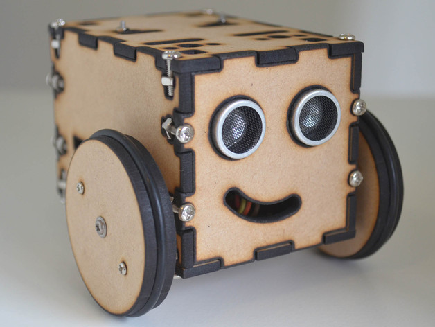
Once all of the utilitarian requirements are covered, the fun can begin. How will you add personal flair to your bot? Giving the bot facial expressions is one way to add personality, and the PopPet (a fully open hardware DIY robot kit) is a fantastic example.
With its interchangeable faceplates, PopPet can express different personalities or moods. Want PopPet to be surprised, sad, happy or even turn PopPet into a cat? There’s a faceplate for that. And since this is an educational robotics platform, there aren’t restrictions on how much you can actually modify the PopPet, making it easy to learn what goes into making a robot without any prior mechanical or stylistic knowledge.
Most engineers pursue designing a robot because they have a task to be automated. While creating practical robots is fun, sometimes designing ones that are impractical can be an even more exciting challenge. Thus, no conversation about robots would be complete without mentioning Simone Giertz’s Shitty Robots. While in pursuit of automation, these craptastic machines make everything worse and more complicated! Read more about her in this TechCrunch post.
Whether you’re making a shitty robot or one that’s potentially award winning, the overall robotics design process is generally the same. From defining the problem, researching and designing, and creating a prototype to building, testing and evaluating your robot, you’ll definitely want this checklist from Galileo to keep your project on track.
How To Start Making Robots
Ok, enough thinking. Let’s do something already! Here are the practical steps to take and the materials needed to really build a real robot.
Robot Kits
Buyer assembled kits are a popular choice for those that want to learn how to build, code and play with robots. This is a great way to initially get into making and also a viable way to sell complex creations.
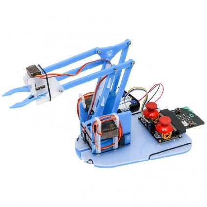
For total beginners, a micro:bit robotics kit is a good place to start. The micro:bit is a microcontroller board designed by the BBC specifically for educational purposes. Thus, this particular microcontroller is the easiest to use when learning new concepts because it uses a programming language called makecode, which is a visual block based language perfect for beginners. SparkFun has a fantastic micro:bit robotics kit, while kitronik can hook you up with a micro:bit robotics arm kit.
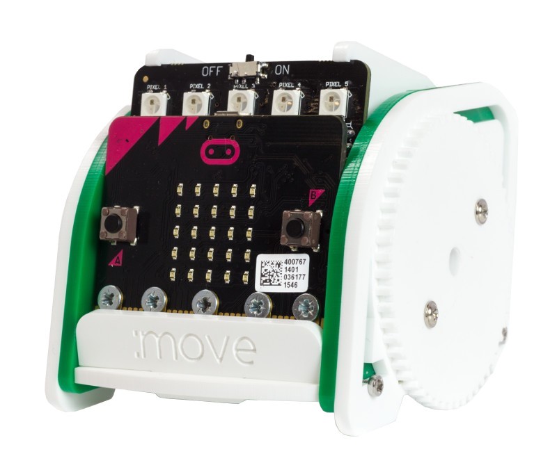
Another fun introduction to robotics for beginners, the :MOVE mini buggy kit teaches users about basic physical computing concepts and how to use servo motors. This two-wheeled robot is suitable for autonomous operation, remote control projects via a Bluetooth application or being controlled using a second BBC micro:bit as a controller via radio functionality. The buggy also has 5 x RGB individually addressable ZIP LEDs (NeoPixel compatible), which can be used as indicators, reverse lights, etc. It’s also possible to add a pen or other extra parts to the kit to increase the range of tasks for which it can be used.
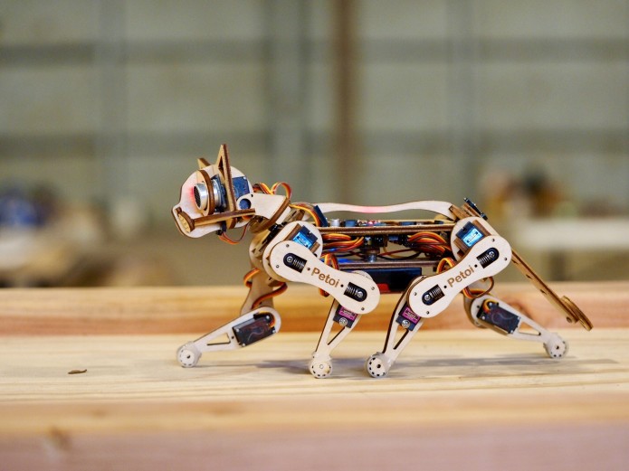
Once you get the basics down, a really neat robot kit by Petoi (who specialize in pet robots) is Nybble—described as the world’s cutest open source robotic kitten. Its purpose is to make programming and robotics easy to learn and understand, all in one adorable package. But don’t let the cute-factor fool you. This is a legit Arduino-driven robot that stores instinctive “muscle memory” to act and react with and to the world around it.
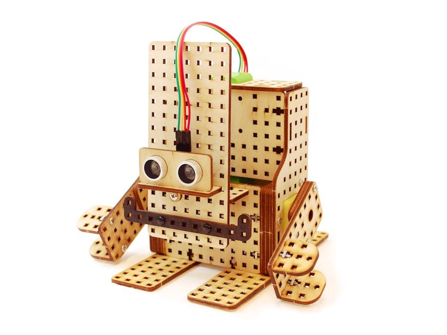
If cats don’t make you purr with delight, then maybe this Gorilla Robot kit will have you swinging from the treetops. This laser cut guy can be controlled with a smartphone or tablet over Bluetooth and programmed to avoid obstacles with a distance sensor. You can also add light sensors to the eyes and program it as a light follower. This kit is a great open-source project for anyone wanting to practice their robotics skills before designing their own beast.
How To Construct A Robot
Once you’ve got a few kits completed, it’s time to graduate to creating a robot design from scratch. It can be quite overwhelming, so why not learn how to make a simple robot by following a tutorial? Instructables is chock full of user-submitted builds for bots of every caliber, and there’s even an online robotics class to walk you through the process.
For even more robot-centric design, the Let’s Make Robots community is not only all about building robots but also sharing the nitty-gritty details and challenges encountered when doing so. It’s really a great resource and has one of the friendliest bot-building communities around.
Robot Design Software
When designing on your own, you’ll need the proper software. Any vector design software is a great beginning tool for making things such as mounting plates and simple chassis, and you can get by for many years using just Adobe Illustrator, a home printer and access to a laser cutter for most designs.
But to make custom robots, you’ll want to add a CAD tool to your belt. This kind of 3D modeling is essential for more intricate designs, and Fusion 360 is a great multi-purpose CAD tool.
If you want to tackle more elaborate concepts without needing a degree in computer science, check out EZ Builder from the EZ robot folks. It is much more accessible robot maker software for tasks such as computer vision and motion control.
Robot Hardware, Parts And Tools
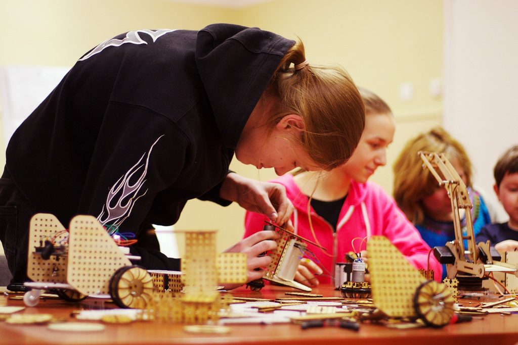
Sure robotics can turn into an expensive endeavor depending on how elaborate your robot’s functionality is, but it doesn’t have to break the bank. For a investment in few tools and robotic accessories (plus access to a laser cutter), you can accomplish a lot with a very little:
Tools
– Soldering Iron
– Helping Hands
– Wire Cutter/Strippers
– Flush Cutters
– Benchtop Power Supply
– Small Screwdriver and Bit Assortment
– Hot Glue Gun
Components
– Battery Holders/Compartments
– LEDs
– Resistor Assortment
– Power MOSFETs
– Toggle Switches
– RC Analog Servos
– Raspberry Pi
– Arduino
Suppliers
Hobby King is one of the best resources for RC components and all things drone related. With a huge catalog, the selection of motors and servos is one of the best for DIYers.
Robot Shop has a little bit of everything. Plus, it’s one of the only resources for the high-end components that you’d struggle to find elsewhere.
Sparkfun not only offers a great selection of components, breakout boards and kits, but it also has tutorials galore plus a yearly autonomous vehicle competition that’s not to be missed.
Adafruit has one of the largest spreads of sensors, displays and components around. Plus, there’s high-quality documentation for nearly everything sold.
Thrift Stores have a treasure trove of old printers (in particular) that are chock full of decent DC motors, gears, pulleys and other mechanisms, all of which are quite salvageable.
Robot Design Ideas
Robotics is a broad field, and there are many types of robots that you can build as a product to sell or use promotionally to build a brand. Here are some of the main classes of robots for inspiration.
Simple Robots
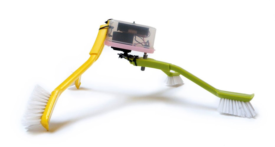
Why complicate things? If you want to skip all that programming business and stick to simple robot ideas, the quite humorous Randy Sarafan has you covered. He’s designed many different simple bots that use a variety of household materials and require minimal wiring.
While his ideas aren’t laser cut, they’re too clever not to include in the discussion. We’re kinda partial to the Skitter Bot, which came into this world “as result of a chain reaction of exploded cosmic energy.” According to Sarafan’s current estimates, this chain reaction took roughly 13.7 billion years to complete. When put into such context, it becomes quite clear just how long it takes for a near-perfect walking scrub brush bot to come into being.
But don’t be fooled by its simplicity, though. This kind of scrub bot didn’t just materialize overnight when Sarafan zip tied a bunch of scrub brushes together. No! “There was an ineffable cosmic plan that led up to this bot’s creation, going back well beyond the day when man, through genetic mutation, first evolved the ability to manufacture zip ties and scrub brushes,” he says. “This bot is a bona fide cosmic child.”
In addition to cleaning, robots can remind all those born without a green thumb to water their plants. These Plant Friends contain a moisture sensor system that monitors the air temperature, humidity and soil moisture of indoor plants, and they send alerts via email or text message when plants are thirsty. Your geraniums will thank you.
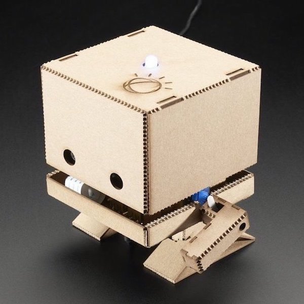
If you like the cute characters above, we’ve got another for ya: TJBot. Born at IBM Research with all kinds of personality, TJBot is a DIY template to learn, experiment and explore AI with IBM Watson. Laser cut this cutie then use the open-source, step-by-step recipes—a.k.a. coding instructions—designed for a Raspberry PI to connect your TJBot to Watson developer services so you can teach it to dance, tell a joke or carry on a conversation.
Wheeled Robots
A robot with wheels is one of the best designs for beginners to tackle. You can get started with just a couple of motors and some decent-sized batteries to roll a wheeled robot along. Wheels allow a quick form of locomotion and are the cheapest way to get bots going.
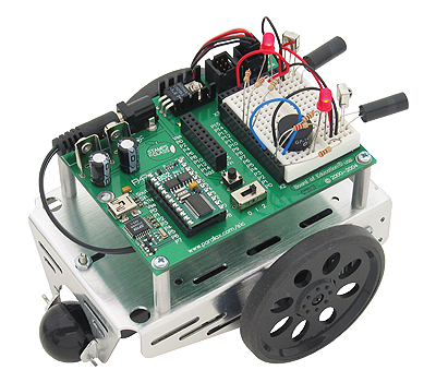
Having two rear-mounted wheels allows for differential steering, which is one of the simplest means of robotic directional control. Parallax’s BoeBot is a very common wheeled platform that offers a lot of features in a standard little package.
Toy Robots
Alright, so there’s not much of challenge when your main hurdle is spending a few dollars on a mass-manufactured robot toy. Not only can you learn from the mechanisms the robot already has, but once your robo-skills have improved, you can tear your store-bought bot apart and use the chassis or precious internal electronics for your own designs. RC cars or tanks are great, cheap ways to get a prebuilt drive mechanism that can easily be expanded upon.
There are toys that you can tear apart and rebuild, but why not start with one meant to be built and rebuilt? The Lego Mindstorms series has come a long way in the past years and is now a powerful, yet accessible, robotics exploration kit. Ignore that age label on the box because this platform is for everyone. It’s a wonderful way to try out new designs without the cost of consumption you’d have with other robots.
For a toy robot that doesn’t have the look of off-the-shelf components, check out this laser-cut basketball robot that gives you a buddy with whom to shoot, score and make the crowd (even if that’s just your cat) go wild. This tutorial is a step-by-step guide for a simple and small differential-drive robot that uses the Intel® Edison. See it in action here. Bonus: You’ll get to know a few more tricks on how to use Mini Breakout Kit and set up a node.js server for the communication.
Combat Robots
If you’ve ever hosted a miniature sumo-bot competition, you know that once the battles begin, it’s really quite thrilling. Building a fighting robot gives your design a better sense of purpose as the goals are clean cut and the stakes are quite high!
To get started, the Sumobot Jr. is a great beginner model that can hone your skills while keeping the budget in check. Get the laser cutting files to build the chassis here.
If you can’t find a local competition to test your new creation, why not start your own? Combat robotics is much more about community than conflict, and would give your newfound group a regular goal to work around that leads to better participation.
Walking Robots
Walking may seem like second nature to you and me, but for robots, it’s one of the most challenging builds.
Bi-Peds: Humans, birds and (occasionally) apes walk bipedally. And there’s good reason there’s not an abundance of bipedal locomotion in nature. Walking upright on two legs is actually a form of controlled falling, and it requires complex synchronization of many different muscles and constant adjustments to control the center of balance. You’ll often see “walking” robots that actually shuffle around with short steps to better keep upright, but some are more than meets the eye.
While building a biped that moves around like a person is a significant challenge, less experienced robot builders can get started with their very first biped with Otto DIY. This sweet open-source robot comes with a downloadable 3D model for printing the body as well as all the electronics/programming you need to get Otto going—from walking, dancing, making sounds and avoiding obstacles. You can build Otto in less than a day and be able to say that you built a functional biped!
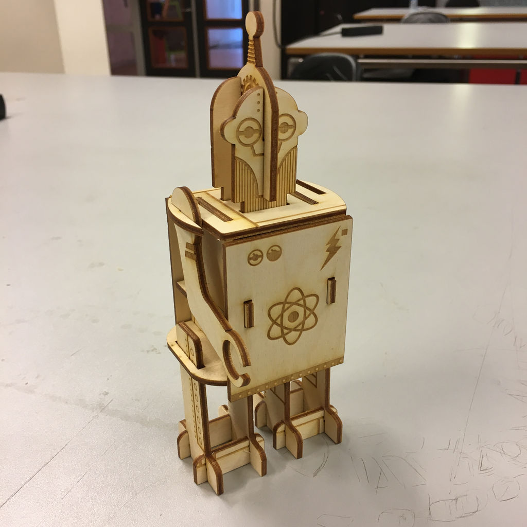
If electronics and programming aren’t your thing, then opt for the laser-cut windup robot made from an example in the book Build Your Own Robots, Assemble Three Robots by Steve Parker and Owen Davey (in Dutch: Bouw Je Robots, Maak Zelf Drie Robots Die Echt Kunnen Bewegen). Get the plans via Instructables here.
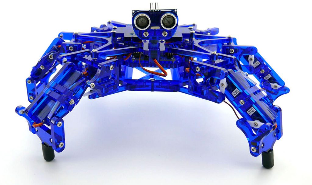
Hexapods: Six legs are better than one (or two, or three…). Hexapods are some of the most common legged platforms since they are inherently more stable, and the algorithms for locomotion are, while complex, still simpler than those required for a tall biped. And once you’ve got it stable, you can do some crazy things with your platform.
If you’d like to tackle one of these electronic insectoids, invest in a few more piggy banks. Since the most common designs require three servos per leg, the price tag for even a basic hexapod can be quite hefty.
That said, there is an affordable build available. Hexy the Hexapod is a fully articulated hexapod robot kit that provides a platform to explore advanced robotics, kinematics and programming. Hexy makes complex robotics less costly, easier to learn with the tutorials and documentation, while being radically more fun—and cute! At the same time, its built with completely open-source hardware and software, making discovery and extension as easy as building it in the first place.
Hexy has six legs, 19 servo motors and is powered by Arduino, while maintaining a price four-to-10-times less expensive than current hexapod robots. Great for students 15+ years old who are exploring advanced robotics and kinematics as well as engineers who are looking for an open-source platform.
Flying Robots
Making drones and racing robots has never been easier and more affordable. Thanks to the explosion in cellphone technology, motion sensors have become faster, cheaper and more capable. Because of these advanced accelerometers, gyroscopes and magnetometers, keeping track of a robot in 3D space is now possible for tinkerers of every skill level.
Multicopter drones require precise measurement of their position so they can hover and produce stable flight. While you can buy individual components for flying robots, it’s increasingly common to find controllers that have most of the electronics integrated, so you just need the motors, battery, remote and a frame (which can be easily laser-cut).
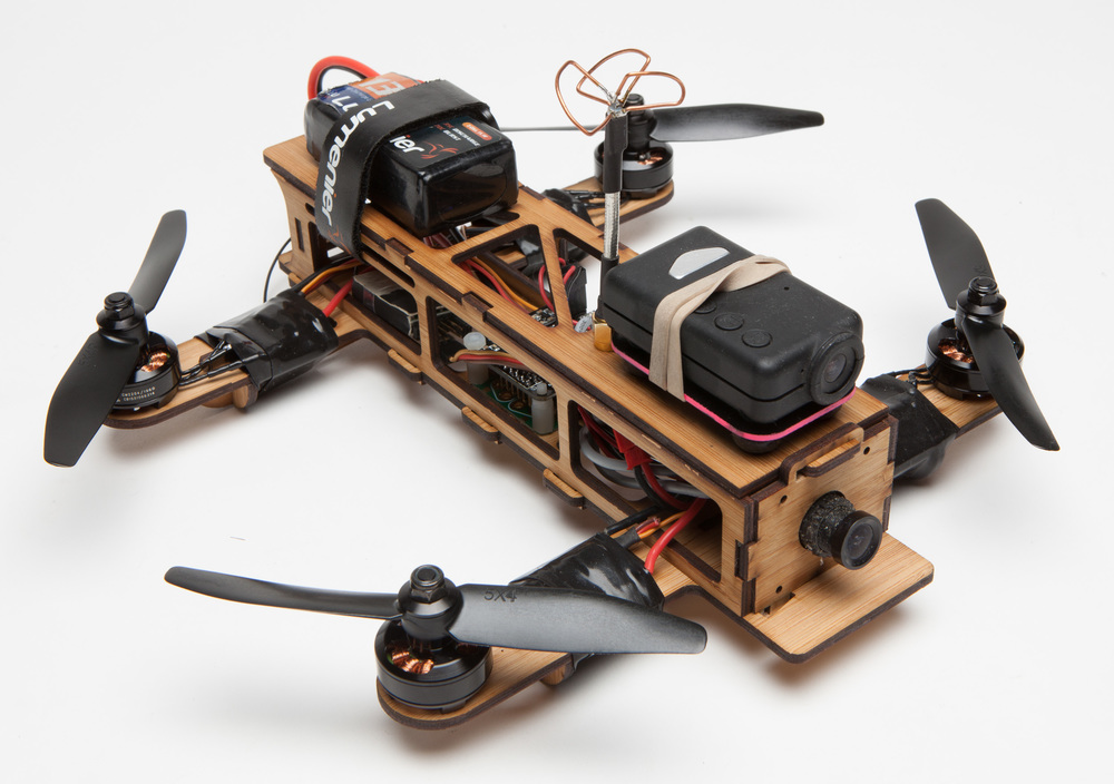
When it comes to drones, the Shendrone by Andy Shen is cost effective with structural material laser cut from bamboo ply, and a snap-fit assembly means no glues or screws to slow down the construction process. That’s about as easy peasy as it gets.
Once you get the hang of flying drones, you might want to strap a wireless camera on board and enter the growing sport of drone racing. These high-speed aerial robotics competitions are quickly gaining popularity around the world. Who wouldn’t want to fly?
Artistic Robots
Don’t worry art students, the robots are coming for your future job, too. But the good news is that you can take a pass on your basket weaving class and upgrade your projects with a basket making robot. Then take all of the inventory and open your own basket boutique. To entice customers to come in, use this friendly bot (made from laser cut MDF) to decorate your storefront windows.
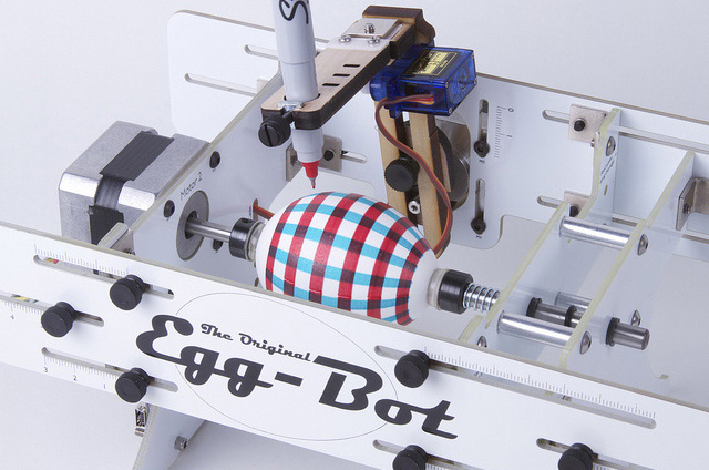
What if your customers want more that baskets? Diversify your product line and start selling custom decorated eggs thanks to this incredible Egg Bot.
Robots With A Purpose
Sometimes we make robots just for the heck of it, and sometimes we make robots to serve a specific function. For example, the laser cut Android Things Draw Bot will take your selfie and then make a drawing of said selfie within minutes, making this one of the best party companions around.
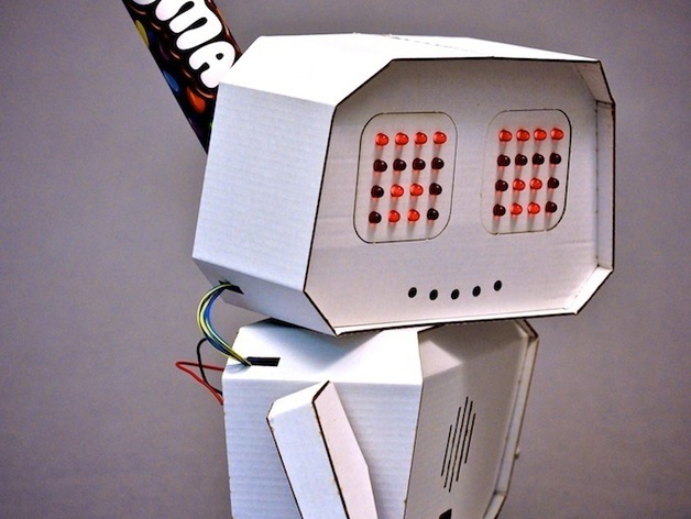
Trying to cut back on your sweets consumption? Or maybe you just want your coworkers or classmates to stop stealing your treats. In either case, the Arduino Ninja Smarties Robot is the robot for you. This open-source, laser-cut robot takes money in exchange for Smarties, M&Ms or Skittles. What a delicious idea!
Builder Robots
Fancy a new wall for your home? Laying bricks is backbreaking work. Thankfully, this robot arm has no back to break and will happily lay bricks in an elaborate pattern so long as it has power…and plenty of bricks, of course.
Need an intricate geometric lattice for your minimalist lair? These “metabolic” robots can assemble trusses for elaborate structures much like organic systems.
Complex Robots
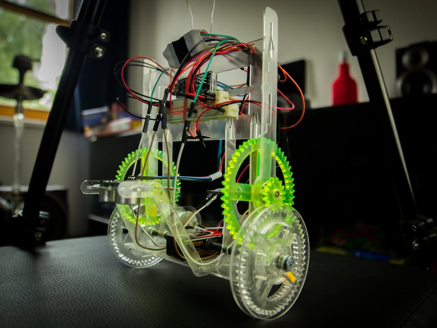
Looking for more of an engineering challenge? Test your skills with the self-balancing robot. It’s laser cut from acrylic—imagine all the color possibilities! In addition to constantly seeking the brightest spot in the room, this laser-cut-gear machine balances itself on only two wheels. It’s a feat in both mechanical engineering and programming.
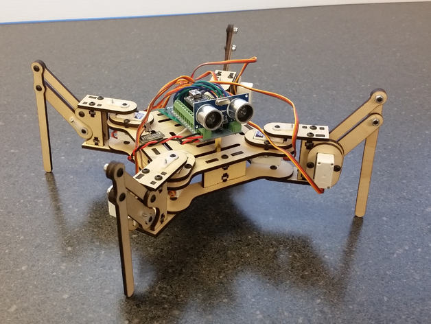
Another ambitious laser cut robot is the mePed Quadruped Robot by Scott Pierce. It features a completely laser cut chassis, four—that’s right, FOUR—legs and eight degrees of freedom. This means the robot can move on the following axis: up and down, forward and back, right and left, and pitch and roll. Pretty complex! This design offers a ton of movement options for your bot and is quite an accomplishment both mechanically, electronically and programtically.
Robots For Branding
It’s easy to imagine being able design, make and sell robots for a profit. But can they be used in branding applications? You bet.
When you’re a tech giant like Microsoft, status quo promotional products for an annual developer conference just won’t do. Event attendees expect more. Much more.
So the company went to the drawing board (literally!) to create the ultimate tradeshow giveaway for its Build Developer Conference—a Sumo Robot.
But this was no easy task. The engineer in charge of the project had never created event swag like this nor designed a custom giveaway on this grand a scale. In fact, many of his peers didn’t think it was possible to pull off the project in the timeframe available. There were so many moving parts, the platform was liquid, the timeframes were light and he was running up against budgetary constraints.
Undeterred, he set out make it happen. Find out if he pulled it off here.
Designing a full-scale operational robot isn’t always in the budget for branding campaigns. So how can you show off your robotics chops on a small scale while still making a big impact? Check out this robotic claw business card and show everyone you’re a robo-ringleader.
Need more inspiration for all the kinds of robots you can make? Pinterest has you covered (as always), and check out this compilation of the 10 best robotics articles.
Bringing Robots To Life
We’ve only scratched the surface of what’s possible in the wide world or robots that you can make to sell or use to build a brand. It’s a very broad and deep field that incorporates numerous facets from both the arts and sciences in order to produce a working thing. That’s the fun of it though, the challenge, the risk of failure and the possibility of bringing an idea to life.
Additional thanks to DJ Harrigan for providing supplementary content and Lisa Horn for writing and content editing.
Once a week or so we send an email with our best content. We never bug you; we just send our latest piece of content:
How to Build Your First Robot ($ 85)
Introduction: How to Build Your First Robot ($ 85)
********************************************************************************
Update: To some 10.000 people who already read this post, I would like to apologize. When I first entered this post, I was way over estimating the prizes, due to the fact that I live in Denmark, where everything is very expansive!
If you have any problems or questions regarding this project, please feel free to contact me at letsmakerobots.com
This is a walk through on how to make an autonomous, self-exploring, «own-mind» (not remote-controlled, not strictly pre-programmed, but reacting to surroundings) robot in a few hours.
It is really easy, and it does not involve knowledge of electronics to get you started with robot-building.
Focus in here is on the absolute necessary to get the basics covered.
This is meant to be an eye-opener, after building this, you can build anything and control any electronic device!
Sounds crazy? It is true, you just need to try it to understand how much power is in some of the chips you can buy for a few bucks today. Welcome to the world of microcontrollers 🙂
Step 1: Buy the Materials (Project Board, Microcontroller and Starter Pack)
Shopping list, start here, by this:
Links are just where I happened to find the items from a world wide web perspective. You can use any (web) shop you’d like, of course.
Prices are approx. As far as possible, try to get it all from the same shop, and from a shop located in your own country etc to get the best deals and faster deliverance etc.
1 PICAXE-28X1 Starter Pack
The 28 pin project board in this package is like a game of Mario Bros; Fun and full of extras and hidden features, making you want to play over and again. This includes the main brain, the PICAXE-28X1.
Price: 38 USD
This is a little expansive, but it is only the first time I recommend you to get this, it includes a lot of nice basic stuff, you get a CD-ROM with lots of manuals, cables, a board, the Microprocessor etc. Actually it is EXTREMELY cheap. Similar packages cost up to 10 times this price!
Be sure to get the USB-version, images in the shops may not match, and show a serial-cable when you are ordering a USB. When buying the USB-version, it is not necessary to get the USB-cable as an extra item, even though it is also sold separately.
Get it here
.
Once you have bought this one time, just buy a new board and accomplishing Microcontroller for future projects, much cheaper, you are a Robot-builder with all the basics done.
Step 2: Buy the Materials (The Motor Driver L293D)
1 L293D Motor Driver
The name says it all, more about this chip later 🙂
Step 3: Buy the Materials (Servo Upgrade Pack)
1 PICAXE Servo Upgrade Pack
-An easy way to get a servo topped with some small parts needed for this project.
You can also get any standard servo, the pins shown on the image, and a single 330 Ohm resistor instead of the yellow chip, if you should wish.
What is a Servo?
A Servo is a cornerstone in most robotic appliances. To put it short it is a little box with wires to it, and an axle that can turn some 200 degrees. on this axle you can mount a disc or some other peripheral that comes with the servo.
The 3 wires are: 2 for power, and one for signal.
The signal-wire goes to something that controls a servo, in this case that is the microcontroller.
Result is that the microcontroller can decide to where the axle should turn, and this is pretty handy; You can program something to physically move to a certain position.
Be sure to get the red/black/white wires for it. This is not allways included, and it is a non-standard socket!
Step 5: Buy the Materials (Motors and Wheels)
2 Gear Motors with wheels
The higher the ratio, the stronger robot, the lower, the faster robot. I recommend ratio somewhere between 120:1 to 210:1 for this kind of project.
Step 6: You Will Also Need, and You Could Also Buy..
You will also need:
Step 7: Lets Make a Robot!
OK! You have ordered the stuff, received your package(s), you want to build 🙂 well.. Let´s get started!
First mount the wheels to your geared motors. And add tires (rubber bands in this case).
An easy way to mount stuff for fast (and amazingly solid and lasting) robots is double adhesive tape.
Step 9: Build the Body Out Of.. Nothing, Really!
Insert the batteries, so you have a realistic idea of weight and balance.
When batteries are below the axel of the wheels you can make it balance, but it is no problem if it does not.
Add some double adhesive tape to the button of the server as well, and..
Step 10: Design Your Robot
Chose your own design, you can also add extra materials if my “design” is too simple.
Main thing is that we have it all glued together: Batteries, Servo and wheels. And wheels and servo can turn freely, and it can stand on it´s wheels somehow, balancing or not.
Step 11: Disconnect!
Take out the batteries, to avoid burning something unintended!
(trust me, you want to 😉
Step 12: Let’s Get Started With the Board.
And now for the main-brain.
You should have a project board similar to the one on the picture.
Notice that it has a chip in it. Take it out. The chip is a Darlington-driver that is quite handy placed there on the board, but we will not need it for this project, and we need it´s space, so away with that chip!
It is easiest to get chips out of their socket by inserting a normal flat screwdriver just below it, move it ind, and tip up the chip carfully.
Step 13: Insert the Chips
A fresh, brand new chip usually do not fit into a socket right away. You will have to press it sideways down on a table, to bend all the legs in an angle so it will fit. (Legs go down, into the sockets :).
Make sure all the legs are in the sockets.
If you bought the Servo upgrade from Picaxe, you have a yellow chip. Put it in place of the Darlington.
Note that not all holes in the project board are filled out with the yellow chip. We only need the eight to the right in the picture, as this is just simple resistors, we do not need to feed them extra.
This yellow chip is actually just 8 * 330 Ohm’s resistors in a neat package. And so, if you should have a resistor, you can just insert it instead in slot numbered “0” (see picture for this ugly little hack), as this is the only one we will use, when we only use one servo.
Also insert the large chip, the brains, the microcontroller, the Picaxe 28(version number) into the project board.
Important to turn this the right way. Note that there is a little mark in one end, and so on the board. These must go together.
This chip will get power from the board via 2 of it´s legs.
All the remaining 26 legs are connected around on the board, and they will be programmable for you, so you can send current in and out to detect things and control things with the programs you upload into this microcontroller. (cool!)
Step 14: Insert the Motor Controller
Now insert the L293D motor-controller in the last socket. Be sure to turn this one the right way just as the Microcontroller.
The L293D motor-controller will take 4 of the outputs from the microcontroller, and turn them into 2. Sounds silly? Well.. Any ordinary output from the microcontroller can only be “on” or “off”. So just using these would (example) only make your robot able to drive forward or stop. Not reverse! That may come in unhandy when facing a wall.
The board is made so smart that the 2 (now reversible) outputs get their own space, marked (A) and (B) just next to the motor-controller (Bottom right on the picture). More about this later.
Step 15: The Red Plastic on the Back of the Board
On the backside of the board you may find some strange plastic.
This has no use, it is just a leftover from manufacturing.
They “dip” the board in warm tin, and parts they do not want so get tinned is sealed with this stuff.
Just peal it off when you need the holes they seal.
Step 16: Connect the Motors Wires to the Board
.. Or if you are that advanced, use some other means of connecting 4 cables to the standard sized holes! (one can buy all sorts of standard sockets and pins that will fit)
If you (like me) just solder onto the board, you can strengthen this part with some tape. or if you have some of that heat-shrinking plastic you can support the wires with this.
Step 17: Connect the Wires to the Motors
The 2 “A” goes to one motor, and the 2 “B” to the other.
It does not matter which is which, as long as “A” is connected to one motor, and “B” to the two poles of the other.
Step 18: Hooking Up the Servo
Now let´s hook up the servo.
If you should read the Picaxe documentation, you will read that you should use 2 different power-sources if you add servos. To put it short; We don´t mind here, this is a simple robot, and to my experience this works just fine.
Yo will need to solder an extra pin to output «0», if you want to use the standard servo connection. Such a pin comes with the Picaxe upgrade pack (a whole row, actually), but you only need one for one servo, and they can be bought in any electronics store.
If your servos cable is (Black, Red, White) or (Black, Red, Yellow), the Black should be to the edge of the board. Mine was (Brown, Red, Orange), and so the brown goes to the edge.
The hint is usually the Red; It is what is referred to as V, or any of these, used in random: («V», «V+», «+», «1»). This is where current comes from.
The black (or brown in my case) is G, or («G», «0″ or «-«). This is also known as «Ground», and is where current goes to. (the 2 poles, +/- remember your physics-lessons?
The last color is then «The signal» (White, Yellow or Orange)
Step 19: Hooking Up the Head
Now letôs hook up ââ¬Âthe headââ¬Â, the Sharp IR-sensor. (or SRF05 if you went for that option)
(If you bought an SRF005 or similar instead, you should look here on how to hook this up, it is different from this!)
There are a million ways to hook up a thing like the Sharp IR-sensor, but here are clues:
Red needs to be connected to V1, that is (in this setup) anything marked ââ¬ÂVââ¬Â, or is connected to this.
Black goes to G, anywhere on the board.
White is to be connected to Analogue input 1.
If you read the documentation that comes with the project-board, you can read how to attach the accompanying ribbon-cable, and use this.
What I have done on the picture, is to cut off a cable from an old burned out servo, soldered in a pin, and connected the whole thing just as a servo. You can use it to see which colors of the Sharp goes to which row on the board.. or one way to do this.
Weather you use the ribbons or ââ¬Âmy methodââ¬Â of connecting the Sharp IR, you should also connect the 3 remaining analogue input to V. (look at the little pins connected on the picture, next to the plug)
I had some jumpers laying, and you can see that all 3 connections left are short cut. (The last pair, not touched, are just two ââ¬ÂGroundââ¬Â, no need to short cut these). If you use the ribbon, you can just connect the inputs to V (or ground for that matter) by connecting the wires in pairs.
The reason it is important to shortcut the unused analogue inputs here is that the are ââ¬Âleft floatingââ¬Â. This means that you will get all sorts of weird readings where you try to read if these are not connected. (to put it short, this is a semi-fast paced walkthrough, we must get to the end 😉
Step 20: Let There Be Life
Now for some fun!
Some how you should get the Red wire from your batteries (+) hooked up to the red wire on the project board (V). And the black (-) to (G).
How you do this depends on the equipment you bought.
If there is a battery-clip on both batteries and board you should still make sure that the «+» from the batteries ends up to the «V» on the board. (Learn more here)
As a note; We are only working with one power-supply here. Later you will want to use same Ground, but both V1 and V2. That way your chips can get one source, and the motors etc another (stronger) voltage.
Install the Picaxe Programming Editor on a PC, follow the manuals to get your Jack / USB / Serial hooked up, Insert the batteries in your (still headless) robot, insert the jack stick in your robot.. enter the programming editor, and write
servo 0, 150
Press F5, wait for the program to transfer, and your servo gives a little yank (or spins, depending on which way it was).
If something goes wrong here, contact mecontact me, or mess with the manuals and ports etc, until no errors are reported, and all seems to work,
To test, try to write
servo 0, 200
The servos disc should spin a little and stop. To get back, write:
servo 0, 150
Now your robot’s “neck” is facing forward.
Step 21: Heads Up & Go!
You’re done building the basics!
You have actually made a robot. Now the fun starts, you can program it to do anything, and attach anything to it, expand in any way. I am sure you are already full of ideas, and you are likely not to have followed me all this way 😉
The design may wary, you may have used other parts etc.. But if you have connected as described, here are some tips to get started programming your robot:
Enter (copy-paste) this code into your editor, and press F5 while the robot is connected:
Note: The code will look a lot nicer once you get it into your editor, it will recognize commands and give them colors.
readadc 1, b1 ‘ takes the voltage returned to analogue pin 1, and puts it into variable b1
debug ‘ this draws out all variables to the editor.
goto main
+++
Now take your hand in front of the robot’s head and notice how the variable b1 changes value. You can use the knowledge gained to decide what should happen when (how close things should get before..)
Now I advise you to put your robot up on a matchbox or similar, as the wheels will start turning.
Enter (copy-paste) this code into your editor, and press F5 while the robot is connected:
One of the wheels should turn in one direction. Does your wheels turn forward? If so, this is the instruction for that wheel to turn forward.
If the wheel is turning backwards, you can try this:
To turn the other wheel, you need to enter
(or the other way around for opposite direction.)
The servo you have already tried.
All the way to one side is:
the other side is:
Here is a small program that will (should, if all is well, and you insert the right parameters for high/low to suit your wiring to the motors) make the robot drive around, stop in front of things, look to each side to decide which is the best, turn that way, and drive towards new adventures.
Symbol dangerlevel = 70 ‘ how far away should thing be, before we react?
Symbol turn = 300 ‘ this sets how much should be turned
Symbol servo_turn = 700 ‘ This sets for how long time we should wait for the servo to turn (depending on it’s speed) before we measure distance
main: ‘ the main loop
readadc 1, b1 ‘ read how much distance ahead
if b1 Add Tip Ask Question Comment Download
How to Make a Robot
Introduction: How to Make a Robot
Hey Everyone! Creative Robotix, now that’s what we like! Have you ever wanted to imagine, create and make your very own humanoid robot with its very own personality? We have, so we did, and we would like to share with you what we have done.
Our Creative Robotix framework is a skinnable robotic platform that enables you to imagine and create your very own humanoid robot with its very own character. The platform is articulated with 5 low-cost servo motors, enabling differential drive with independent head and arm movements. A set of three bicolour LED’s and speaker allow for designs with colourful facial expressions and a voice to match. The platform also knows where things are, like lines on the floor and if there are obstacles in front in the path of travel. It is powered by an Arduino Nano and has Bluetooth connectivity, which allows you to program the platform to operate in a few different modes. In full autonomous mode the platform makes for a happy little robot independent and carefree, in interactive mode the robot can connect to your mobile phone and you can play with it, or in super smart mode, you can give your robot a ‘Brain the Size of a Planet’ (as Marvin, the Paranoid Android, a fictional character in The Hitchhiker’s Guide to the Galaxy series by Douglas Adams was said to have) and hook it into the cloud of things via your PC where it can access internet knowledge and talk to other cloud connected Creative Robotix robots out there and share experiences. The options are limitless.
Our design philosophy is based around the 21st Century Robot Project an open source, crowd sourced framework approach to building robots in the 21st Century where robot’s are imagined, designed and built to be social, to each have a name, to be community driven, connected, evolving, growing, improving over time, with each contribution and each iteration.
To get you started we’ve included the open source skin, Timmy, which you can customize with your own artistic skills. Timmy, is cute humanoid robot with attitude, he likes reading, drinking coffee, watching ducks fly past while at the park, trying out for the local football team and enjoying a relaxing evening read at home after a busy day
We encourage you to customise Timmy, to give him his own personality, look and style, so why not print him out in white and let your artistic creativity go wild! Alternatively, why not dress him up, and take him out to see a show?
The Creative Robotix base frame is skinnable, so why not show us your design skills and create a new robot character of your own, and perhaps write a creative story about your characters antics using some Science Fiction Prototyping, for more head on over to the Creative Science Foundation. If you are technology minded, then why not try to find new ways to power our platform, perhaps with some of the latest advances in embedded technology, for example CHIP or Pi-Zero and why not try out some other neat sensors, maybe a camera, positioning or even give our platform a sense of smell, or try out adding some other off-the-shelf technology you prefer. By evolving our design, creating your own robots, we hope that you will enter into the spirit of free-sharing by offering your designs back to the community so our Creative Robotix project can fulfill its vision for creating an an open source, crowd sourced approach to building and exploring the future of robotics with Timmy and Friends.
Finally, we wish you, «Happy Imagining, Happy Creating & Happy Making!«
Step 1: What You Need, the 3D Parts
The design files are split into two, the CR Base set forms the Creative Robotix robot base which can be ‘skinned’ to take on different robot characters. The Timmy file set is a character ‘skin’ which can be applied to the base. Download the design files and print them. We have tested these files on an UP BOX, printing in PLA. If you don’t have access to a 3D printer then you might like to try the following online service 3D Hubs.
Tips that worked for us:
Attachments
Step 2: What You Need, the Components.
The materials can be bought from local electronics shops or online. We have used eBay to source components at the cheapest possible retail prices and have found the quality of components to be both good and reliable. A few of the components need to be bought in bulk and so the individual cost is relatively high when compared to the base unit cost. However, this is good encouragement to gather a group of friends and or classmates to share a social build together. The EXCEL sheet will automatically adjust the quantity and order counts according to your group size. Also if you find a cheaper source and component combination, please let us know.
Attachments
Step 3: What You Need, Basic Tools, No Soldering Required.
A set of basic tools, the pair of long nosed pliers will come in handy when assembling the head and the Bluetooth module.
Step 4: Assemble the Lower Body and Line Sensors.
The line sensor modules should snap snugly into place, held by the lower sensor indents. Use five 6mm washer head screws to secure them to the base, they are self tapping, a firm press down on the screw driver will see them sink into the plastic. Hold the screws carefully to see them home.
Step 5: Fix the Battery Cover to the Upper Body.
Open the battery case and separate the battery cover. Using a small screw driver, make a ‘pilot hole’ in the center of the battery cover. Be slow, be gentle. Placing a small square of insulating tape over the center will prevent the cover from shattering. The battery cover should fit snugly against the bottom of the battery bay on the body, secure the rest of the way with a 6mm self-tapping screw.
Step 6: Attach the Lower Body to the Upper Body.
Press fit the ‘body-lower’ and the ‘body-upper’ parts together. We have found the parts to fit quite tightly together, so press firm, so far we haven’t broken any parts at the step.
Step 7: Mount the Drive Servos and Wheels.
Fit the 360 servos in position. They should press fit and hold in place. Use two 8mm self tapping screws to fix the wheels in place.
Tips that worked for us:
Step 8: Attach the Castor Bar.
Put a few spots of glue at the tip of the castor and push fit into the body, the top of the castor should appear flush with the front body. Add a few more spots of glue at the meeting point to secure.
Tips that worked for us:
Step 9: Tidy the Driver Wires.
Fix the wires from the drive servos in place with a plastic cable tie.
Step 10: Plug the Battery Wires.
Strip back the positive and negative wires to bare about 2-3mm of core. Place the positive wire in one of the female connector terminals so that the PVC is just under the top most ‘wings’ of the connector. Gently, but firmly, crimp the ‘wings’ to securely hold the PVC wire in place. Wrap the core tightly around the lower part of the connector under the wings. Repeat for the negative wire. Insert the wires into the 3-pin header blank. Note that pin 1 is denoted by an ‘arrow’, the negative connector is placed here, the positive in the middle.
Tips that worked for us:
Step 11: Fix the Battery Mount to the Battery Casing.
Ensure the top of the battery mount (with the posts spaced furthest apart) is mounted flush to the top of the battery compartment that holds the batteries and is centred. You may need to press firmly to for a few seconds to ensure a firm and even hold.
Tips that worked for us:
Step 12: Upload the Test Script to the Arduino Nano.
If you haven’t done so already download and install the Arduino IDE and base. Connect the Arduino Nano to your computer and open Timmy’s Creative Robotics TestScript in the Arduino IDE. Select ‘Tools’ and then set the options ‘Board’ to ‘Arduino Nano’ and the ‘Processor’ to ‘ATMega328’. The test script makes use of the New Ping library, to install the library, select ‘Sketch’, then ‘Include Library’ and ‘Manage Libraries’. Search for ‘New Ping’ and install. New Ping will conflict with the Tone functions, so you will need to edit the NewPing.h file and set the TIMMER_ENABLED setting to ‘false’. You will find the ‘.h’ file under the ‘Arduino/libraries/NewPing’ folder, usually in your ‘Documents’ folder.
Attachments
Step 13: Fix the IO Breakout and Arduino Nano.
Use a small screwdriver to create pilot holes in each of the four battery mount posts. Secure the IO breakout with four 6mm screws, and fit the Arduino Nano. Attach the main battery compartment to the main body.
Step 14: Wire-up the Line Sensors.
Strip 5 pairs of 3 wires from the main set of patch cables. Feed through the 5 pairs first, then connect the line sensors and tidily pull through. Facing front, the line sensors are numbered from 1 to 5, left to right. This will be important when connecting the other end of the cables to the Arduino breakout.
Tips that worked for us:
Step 15: Mount the Arm and Head Servos.
Feed the head servo cable through the fittings as shown. The servos should fit snugly into place.
Tips that worked for us:
Step 16: Feed Through Ultrasound Wiring, Connect Up the I/O and Tidy Up.
Strip off a group of four wires from the main patch cable set and feed the group of wires through the same opening at the line sensors, this maybe a tight fit, be gentle, but a firm push and some dexterity maybe needed here. Turn the base over and connect the motors and sensors according to the pin mapping PDF. To tidy the wiring, remove the screws securing the I/O breakout the the battery mount. Tidy the line sensor, battery and servo wires into the space made by the battery mount, between the main battery holder and the bottom of the I/O breakout. Fit back the I/O breakout. Secure wires each side of the battery mount using cable ties.
Tips that worked for us:
Attachments
Step 17: Mount the Ultrasound Sensor and Front Body.
Step 18: Assemble the Arms.
Thumbs Up! Using two of the long servo arm mounts from the Tower Pro secure them to the upper arms with two 6mm self-tapping screws, trim, then assemble arms as shown with two further 6mm self-tapping screws at the elbows.
Step 19: Assemble the Head Mount Bracket.
Mount the remaining long servo arm to the head mount bracket using two of the small 4mm servo screws.
Step 20: Fix the Eyes and Mouth.
Using the long nosed pliers, fit the 5mm LED plastic mounts into each eye socket and mouth, they should push through so that the rear clasps protrude through into the rear of the head cavity as shown. Wrap the leg of one 220 ohm resistor around the middle leg of each LED. Fitting the LED’s is best accomplished by using the long nosed pliers again, this time to hold the plastic mounts in place while pushing through the LED from the rear, you should notice a firm solid ‘click through’ when they are correctly mounted. Ensure that both LED’s are fitted with the same vertical orientation to their legs. Here the short outer legs were top most.
Tips that worked for us:
Step 21: Connect the Common Cathode LED Pins Together.
Twist the other ends of the three 220 ohm resister legs together. Trim the excess back, enough for one female jumper cable to be fitted.
Step 22: Wire-up the Facial Features.
Strip off a a group of 7 patch wires from the main patch cable set. Take two and cut in half, bare the core at the ends and twist together. Take a further two wires, and remove the female connectors right at the very end. Bare the core and connect one to each of the twisted pair. Use the isolation tape to secure the connections. Connect the wires, one pair to form common green, one pair to form common red, and one wire to the combined resistors to form common ground.
Tips that worked for us:
Step 23: Fix the Head Mounting Bracket.
Use the cable tie to secure the eye and mouth LED wires, ensure maximum and equal length as possible.
Step 24: Wire-up the Speaker.
The speaker we illustrate here required soldering. Some speakers will have ‘ear tags’ or ‘tags with holes’, if either is the case then simply wrap the bare wire core securely around the tags. Alternatively, you can buy speakers with wires already attached.
Step 25: Fit the Speaker Resistor and Connector.
The speaker is 8 ohms. If we connect this directly to the Arduino, it will draw too much current and risk damaging the output pin. We need to place a current limiting resistor in series with the speaker, using a 220 ohm resistor. Strip back the negative wire to bare about 2-3mm of core. Place the negative wire in one of the female connector terminals so that the PVC is just under the top most ‘wings’ of the connector. Gently, but firmly, crimp the ‘wings’ to securely hold the PVC wire in place. Wrap the core tightly around the lower part of the connector under the wings. Repeat the same procedure for the resistor, instead of wrapping the resistor lead around the lower part of the connector, simply trim it back, ensuring the upper wings are tightly holding the resistor securely. You may also crimp down the lower set of wings. Push the negative connector into the ‘arrow’ indicated outer position of the 3-pin header blank, leave the middle one empty, and push the resistor connector into the other outer position. Strip back the positive lead to bare the core to the top of the resistor, then wrap the core around the resistor lead, then wrap the resistor lead around the two PVC core to secure. Use a small piece of the electrical insulation tape to finish.
Tips that worked for us:
Step 26: Fix the Speaker to the Right Side of the Head.
Use a small piece of blu-tack, or double sides pads here. We used blu-tack which works well. Fix the speaker wires with a cable tie.
Step 27: Assemble the Bluetooth Module.
The Bluetooth module we are using operates on 3.3 volt signalling, the Arduino board we are using operates on 5 volt signaling. The 3.3 volt transmissions from the Bluetooth module to the Arduino are fine, in 5 volt logic a logic 1 is seen as a voltage greater than 2 volts, so we’re all good. However, the 5 volt transmissions from the Arduino to the Bluetooth module may cause very bad things to happen to the RX input, over driving the input potentially causing damage, so we need to regulate these transmission voltages down to an acceptable level. This can easily be achieved with a ‘voltage divider’. In this case we need to bring 5 volts down to 3.3 volts, so we need a 20K resistor across the modules RX input to ground and a 10K resistor from RX the input. The RX input will connect to the the TX output on the Arduino Nano.
Step 28: Prepare the Transistor.
We need to create a ‘bus’ line for the serial TX output on the Bluetooth module, this will allow us to have the Bluetooth module and the USB serial device connected together at the same time, although we may only use one at any given time i.e. the USB serial device is used to upload new programs to the device, and when running, the serial Bluetooth module is used for communication. To implement this ‘one line bus’ we need to use a transistor. Here we use one PNP, 2N222A transistor and a 10K base input resistor.
Step 29: Attach the Transistor to the Module and Wire-up.
Using the long nosed pliers connect the transistors Emitter to the Bluetooth module. Ensure there are not short circuits. Strip of a group of 5 wires from the main patch cable set and connect the to the Bluetooth module. Loop back and secure the cable with a cable tie. The unconnected transistor leg connects to the RX input on the Arduino Nano and the base resistor on the transistor connects to the RX enable line on the Arduino Nano.
Step 30: Install the Bluetooth Module.
Connect the Bluetooth module cables using the pin map guide in the previous steps. Remove the Arduino Nano and run the Bluetooth cable along the cavity, replace the Arduino to secure the cable in place.
Step 31: Attach the Head and Wire Up the Eyes, Mouth and Speaker.
Ensure that the servo motor spindle is centred before attaching the head, follow the pin map to connect the speaker and LED’s.
Tips that worked for us:
Step 32: Attach the Arms.
Role the servo spindle backwards until it reaches its end-stop, then attach the arms using two 4mm screws. A magnetic screwdriver head will make it easier to guide the screws down the arm spindle.
Tips that worked for us:
Step 33: Build Done! Let’s Test the Basic Functions.
Ensure the power switch is in the ‘off’ position. Insert 4 AA batteries into Timmy, any AA batteries will do, however we recommend to go green and use rechargeable ones. Place Timmy on a flat surface, or low pile carpet, then flip the power switch to ‘on’. If all has gone well, then Timmy should spring to life and run through the test script loaded earlier.
If nothing happens, or things don’t work out as they should, don’t worry, just flip the power switch to the ‘off’ position. You will now need to ‘debug’ Timmy to help to work properly. He’s probably just got a few of his wires crossed, so carefully check through the connections, a VCC (+5 volts) or a signal wire may have connected to a GND (0 volts) point, or visa versa. If you can see nothing wrong, then remove all wires from the Arduino Breakout I/O board, and then add them back, one sensor at a time, until you have them all connected and working.
Debugging, or problem solving, may take time, but it is a very useful skill to acquire.
Step 34: Setup and Test the Bluetooth Connection.
Open your computers Bluetooth and scan for the HC-06 Bluetooth module, there the connection PIN should be four zero’s. You may choose to name your connection. View your Bluetooth devices and select properties, then select ‘Hardware’ in the properties window. Note down the COM port number for the Bluetooth module, in this case it’s on COM32. For the purposes of the test, remove the USB cable from Timmy. And flip the power switch to ‘on’, wait for Timmy to go through his little forward and back ‘dance’ routine. Then open the Arduino IDE, select tools, the correct ‘Port’ number, then ‘Serial Monitor’. When the Serial Monitor opens, select a ‘baud’ rate of 9600 and change ‘no line ending’ to ‘Both NL & CR’. You should now see the screen scroll with sensor information Timmy is feeding back you you, play around with the sensors to see the screen output change. You can also send messages to Timmy, try typing a message to Timmy in the top window and press return to send.
Step 35: Congratulations! Your Creative Journey Has Just Begun!
You now have your very own Timmy humanoid robot to play with, to program, to customize, to use at home, to use in class, or for your university project. Let us know what you do with yours!
We will be uploading some standalone sample applications and driver software for different platforms, including Python, C/C++, ROS and Android.
Lastly, we wish you,
«Happy Learning. Happy Playing & Happy Experimenting!«


/images/MARCH/Learn-Robots-Main.jpg)


